Board Assembly
![]()
![]()
![]()
![]()
![]()
|
Board Assembly
|
|
Last update, December 14, 2007
Putting It Together
Parts: SS Machine Screws and Nuts - 4-40 works, stock item SS 3mm nuts Eyebolt 2 of 3 needed- #144, MMY Eyebolt (2)- #140, MMY Single Pulley - #250, MMY Single Deck Pulley - #253, MMY Shackle (2) - #296, MMY Winch and drum, RMG, CPM, RMD Winch bracket, Mike Zellanack Jib servo and HD arm, Servo City Futaba 9405 used here Rudder servo, Servo City Futaba 9350 used here Toggle switch STSP, Radio Shack Radio RX, Servo City Acetate sheet or of sorts, plastics store Small plastic tubing or straws
Tools: Drill 4-40 nut driver OptiVisor is a nice tool scissors Assorted common tools Soldering iron Solder Shrink wrap Nylon ties Velcro
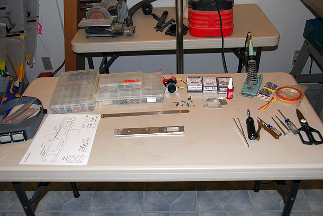
Today we will install all the system board items that will makes this puppy the star in your life. By now you should have all the parts in stock and have good idea where you are going. Set up a clear table with good light and all your stuff around.
The first is to change something into what we want. This will be the single pulley mount and the dual pulley mount. The latter is being done now while we are at the process but will not be used till we get into the sheetline system.
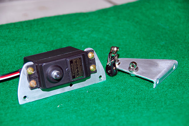
Take two of the long eyebolts and drill out the eye with a #48 drill bit. This will make a hole that will perfectly fit the mounting screw in the shackles. Now you can mount the pulley and shackle to the shackle on the eyebolt. The photo tells you the result. Set the dual pulley set up aside for later.
The Outrigger Install the pulley assembly into the outer hole on the Outrigger with nuts atop and below to set the height. The will be for the bungee return point to the collector point. You will see the schematic in the Sheetline section. Loctite and tighten the shackle screw so movement of the pulley is very stiff. Align the eyebolt so the pulley easily points toward the bow and at the end of its threads. This is to mitigate any rubbing on the hull. The Outrigger will be bent slightly later for this reason.
Install the stubby eyebolt upside down (not as shown above) into the inner hole with a non-abrasive spacer. This is to stand the eyebolt off the mount and prevent fraying damage to the mainsheet line. Minor drilling will be needed for this bolt. This will be the mainsheet line guide as it comes from the collector and the open end should be pointed toward that point. (Frankly, at this point it is not known the line angle to the eyebolt)
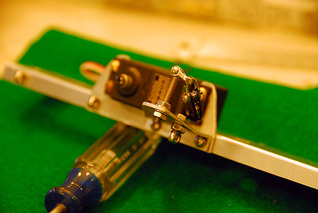
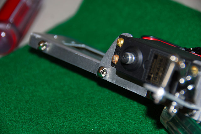
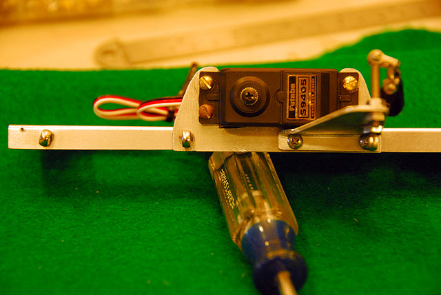
J ib Servo RackInstall the jib servo into the rack with the arm mount to the rear.
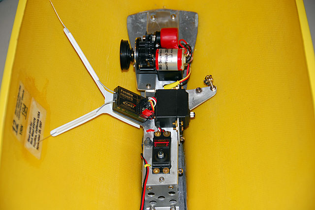
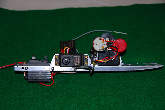
Install the Two Together Place the jib rack against the flange of the platform then the Outrigger outside of this and bolt in the forward two. install a stubby eyebolt in the aft servo mount hole. This may be a sheetline guide for the main from the Outrigger. You will note in the photo there is another eyebolt in rear of the chassis. It is not known which will be used at this time, likely the rear one. We will know in the Sheetline section. "This is called winging it in the shop while updating a website, Vern."
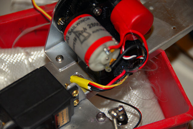
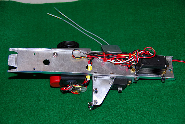
Install the Winch Bolt the winch to the bracket and then to the chassis. Route the wires through the wiring hole and shrink wrap to tape so there no chaffing in the hole.
About Wiring Wiring needs to accommodate at least a three amp (3a) load. This means 25-22 AWG wire for the chassis, batteries and power switch. Chassis wiring must be as shown in the diagram below.
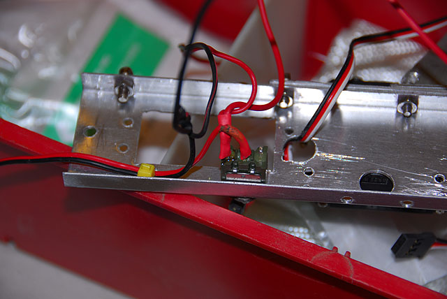
Install the Power Switch We like the switch toggle to be forward when the boat is on and aft when off. This will mean the aft two pins will be wired. The wiring for the EC12 is shown here and recommended by RMG. If you have read Phantom of the Bilge in Dummy Reflections you will know why.
Wire the battery plug red lead to the center pin. Wire the RX red lead and the RMG red lead to the aft pin. Solder the battery black lead , the RX black lead and the RMG black lead together. If you are into shrink wrapping set it up before you solder. If not, tape everything. Leave the wiring loose and we will organize it later.
Don't let the wiring diagram confuse you because it has a double pole switch. Be sure to cut or remove a section the red lead of the RMG plug. The RMG will not work otherwise.
Install the rudder servo.
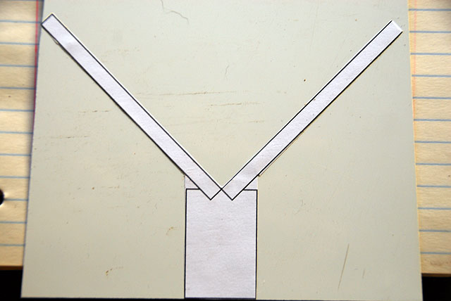
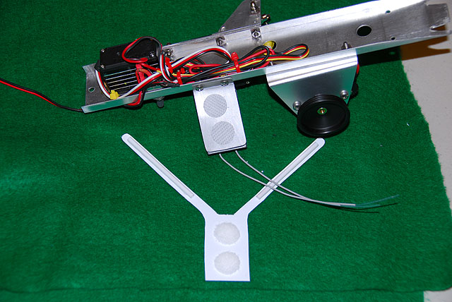
RX Rack Make a rectangular pattern of the RX rack that is not bolted to the chassis on a piece of paper from your drawing. From the center of the top extend two arms at 45 degrees and 95mm long. Cut it out and glue stick it to a piece of stiff acetate or cheap binder cover from Staples. Cut it out and trim to fit.
Find some tubing stuff that is not heavy...anything will do like small straws or some shrink wrap. Cut two about 60mm and crazy glue them to the center of the antenna arms as shown here.
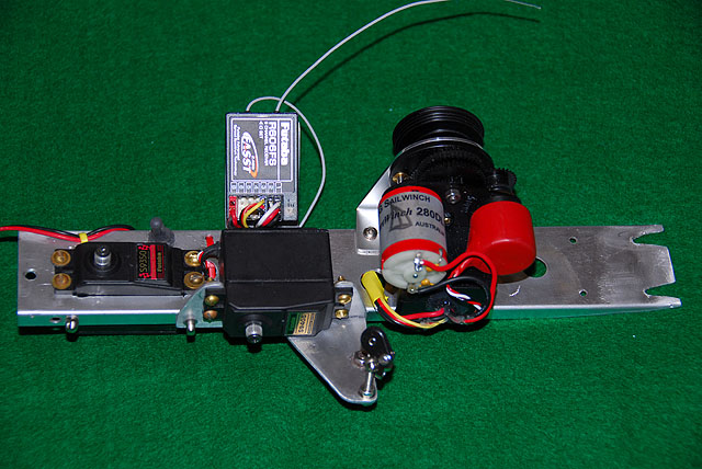
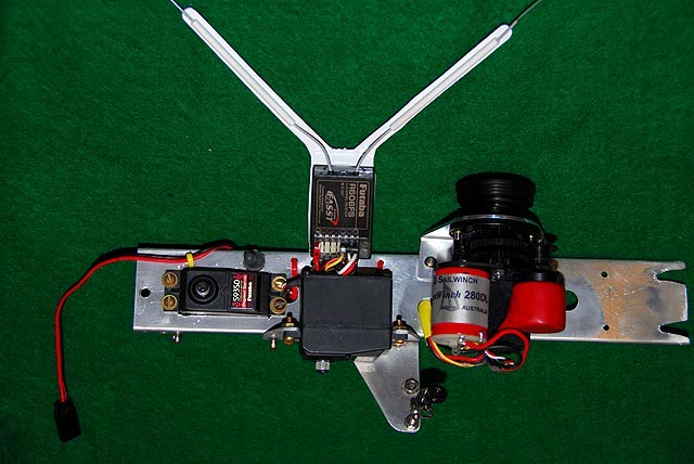
Set up a strip of Velcro on the rack and the RX. Bolt the rack to the chassis. It is suggested to lightly Velcro the antenna support to the underside of the RX rack. This will allow removal during maintenance so it is not damage. Removal may aid in providing more room for handling the antenna leads.
Now route all the wires to the RX for sizing and organize the wiring under the chassis. Leave enough tag to the plug side so you can remove and plug in conveniently. Two reasons: The RX should be lifted off the rack to insert and remove the antenna leads while the support remains in place. You should handle them as little as possible. Also the wiring hole for the RX is sized for only one plug lead at a time, in or out.
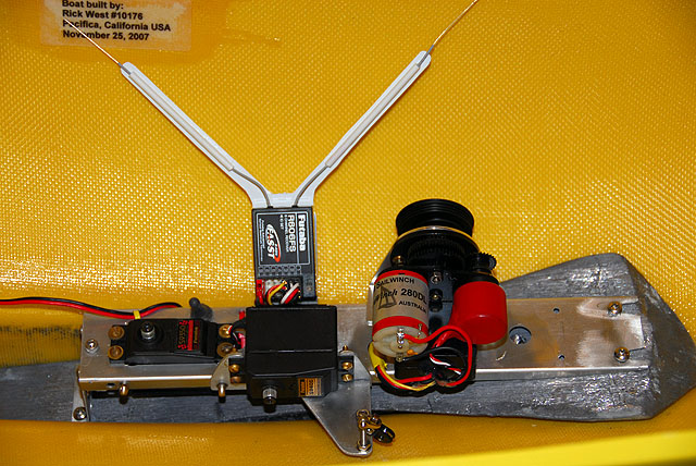
Look At That !! You're outta here. A check of the your work here will be later when installing the sheetline system to the chassis. |