Rinehart Deck Jig
![]()
![]()
![]()
![]()
![]()
![]()
![]()
![]()
![]()
![]()
|
Rinehart Deck Jig
|
|
Last update, July 19, 2004
Editing note: This page has not been edited from the date show above. It is retained here because the tool can be beneficial to those building boats with the traditional framing for a planking deck...Rick West, December 2009
Parts: 1 – stick 1” x ¼” x 12” 3 – sticks ¾” x ¼” x 48” 4 – sticks ½” x ¼” x 48” 1 - sheet 3" x 1/4" x 48" 22- #8 sheet metal screws 1-1/2” to 2” long ¼” shrink tube Epoxy glue
Deck Jig Sizing Chart
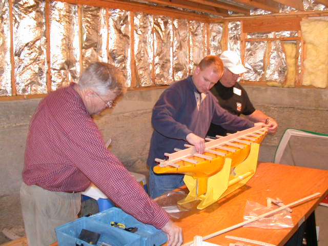
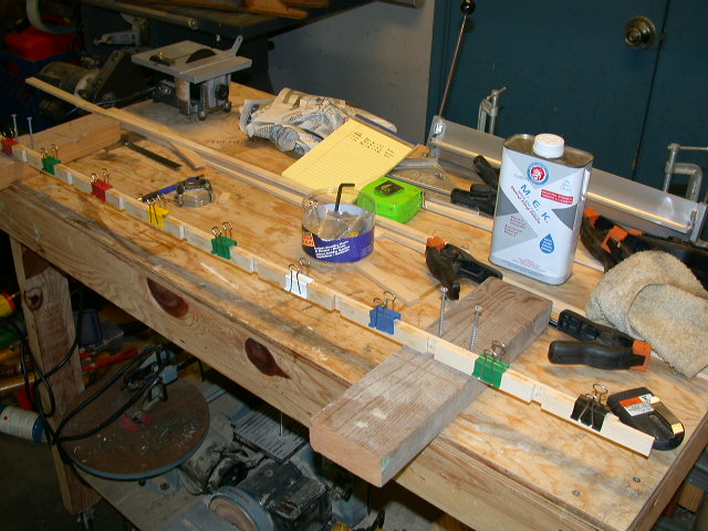
The Deck Jig is the innovative design of Mark Rinehart for a consistent construction process in hull beam measurements and deck alignment. It is estimated this tool will cut more than half the stringer installation time while providing a positive placement of the ribs to your liking. What is shown here is a copy, in principle, of this tool.
This is an optional tool for the advanced user. If you are part of a group that builds one boat or more boats a year, this might be useful as a loaner.
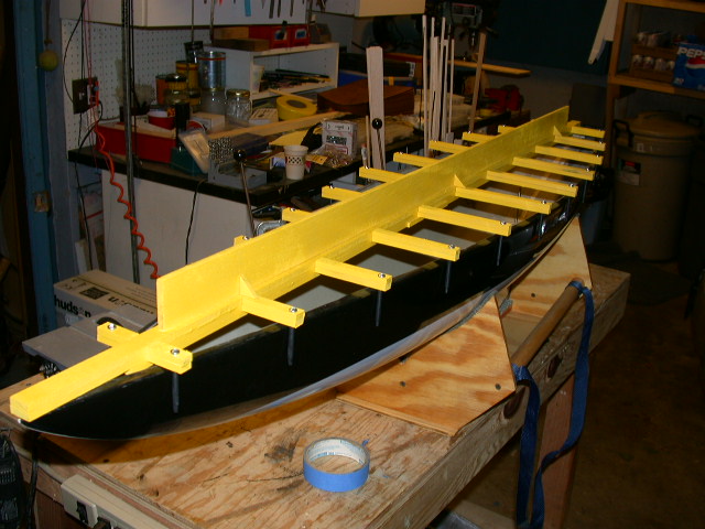
A rigid jig is made of ¼” Basswood stock. This jig will span the centerline of the hull and be aligned to the bow where all measurements begin. Despite the sway of the EC12 hull design, the jig will be straight and provide the reference for all the ribs at the same height. This in turn establishes a deck that is straight for alignment of the mast and the reading of trim angles. It will also be noticed that the mast step will be about 1/2” higher than the previous deck lines that followed the sway of the hull gunwales. This is a major improvement in construction technique.
The span of the tool is to have all eleven beam stations identified with cross pieces fashioned to overlay the hull with the “On Center” beam specifications of the class rule. This is to mean that the jig is measured to be at the center of the ½” tolerance allowed in the rule. The jig will rest on the top of the hull at the bow and the transom. It can be taped to centerline when in use or clam shell clamps can be fashioned from the Basswood stock to lock the jig at the bow and transom using the gunwale flange. What is shown here will be taped for the time being but room has been provided to add the clamps later if desired.
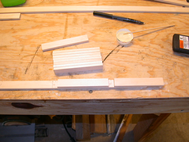
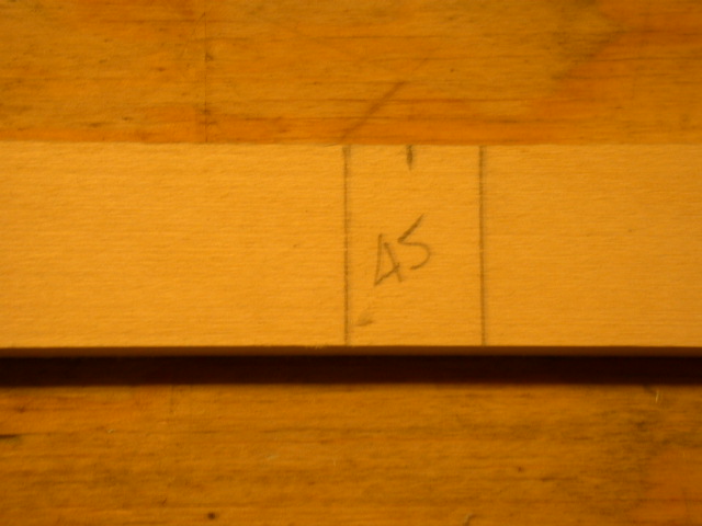
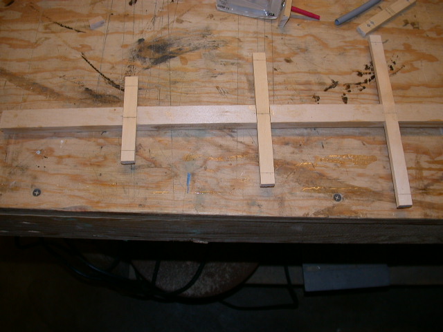
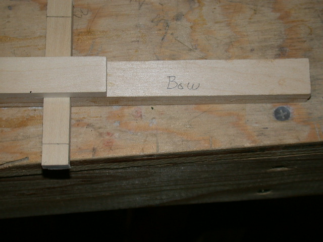
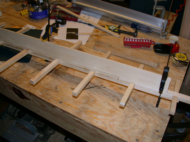
Process One 48” base stick was measured from the bow end at 5” centers through 45”. These marks were then measured ¼” both sides of center and penciled with a square. This will be the location of the beam cross pieces.
1 each stick was cut to 4-3/4” for the bow to the station 5. 10 each sticks were cut to 4-1/2” that would go between the stations to support the beam sticks.
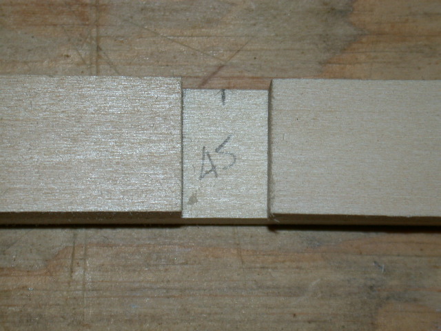
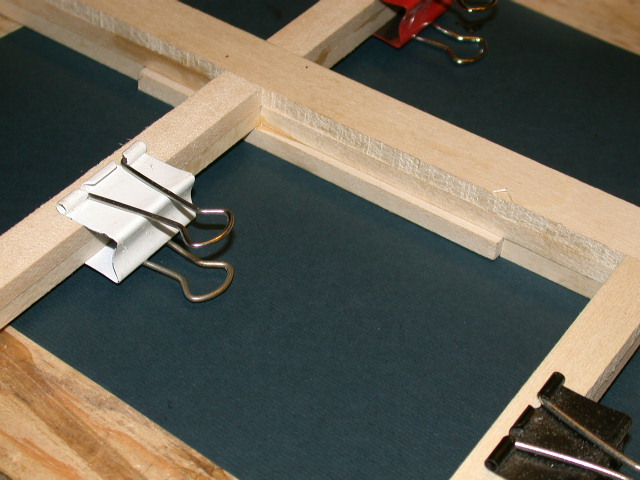
A small cripple of 1/2" x 1/4" was cut to snug up the spacers. The spacers were glued in and held with paper binding clamps. Note that a 4-1/2” spacer will overhang aft of station 45 to receive another piece for the base to continue on to the stern.
Note: Monitor any clamp during gluing as parts can move due to clamp tensions.
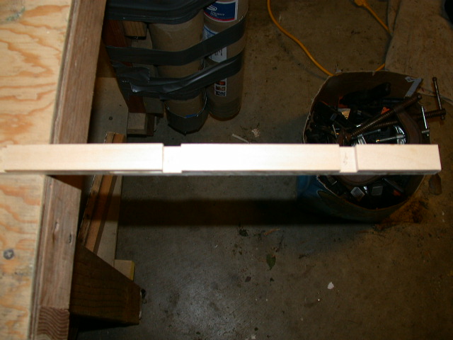
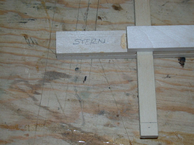
A 9-5/8” piece was spliced to the base, aligned with the cripple and glue to the spacer aft of station 45. This will complete the base to the transom. The final 4-1/2’ spacer is installed to station 50 and a final piece is cut and installed beyond to the transom end of the base.
Visualize that the base will be the top of the jig and the construction is being done upside down.
The ½” x ¼” beam pieces were cut for each station. Before this was done a chart was developed to make sure the inside measurement from the screw, with the shrink tube on it, to the centerline of the jig was the beam specification on center. The chart is provided here in Excel format so you can change it or .pdf format for printing. While you can use the same numbers your screw size may not be the same and it is suggested you run a test before you drill the beam pieces.
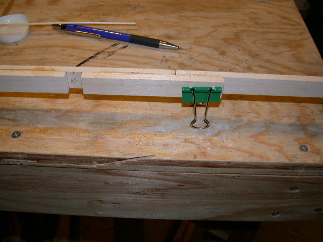
Each piece was cut one inch longer than the on center beam specification. A line was drawn at the center span. The measurement out from center was ½ the beam specification plus compensation for the screw diameter and shrink tube. In the case here that was .07 inches. Hence, the drill point for 1.24 (1/2 beam for station 5) was 1.31 inches as an example. Therefore, a line was drawn for the drill hole measured out from the center span.
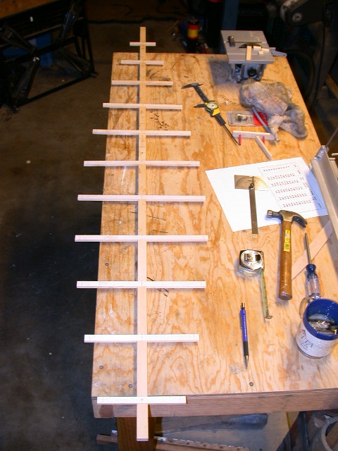
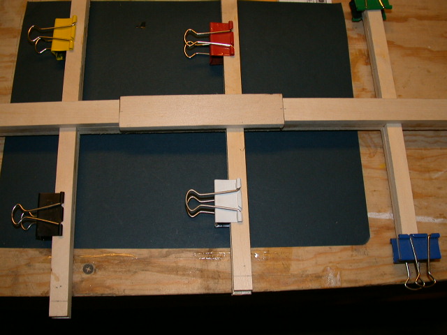
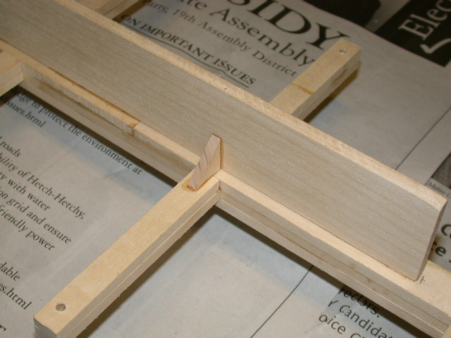
The center of the spacers were marked and the beam pieces inserted and aligned to the center span mark, then glued in with the pencil marks facing up. A mark was made at station 23.5 and 28.5 and a piece of 1”x1/4” was centered over the ¾” spacers and glued in. This will provide the center slot size for stringers 24 and 27.5. Glue in a 19-1/2” piece of ¾” x ¼” stock over the beam pieces forward to just beyond station 5. Make another piece to do the same aft to just beyond station 55. These are short of the full length and provide room for installing clam shell clamps later if you like.
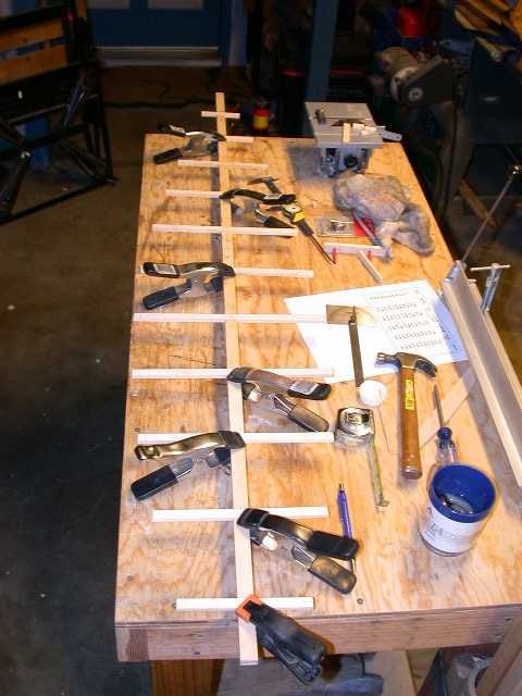
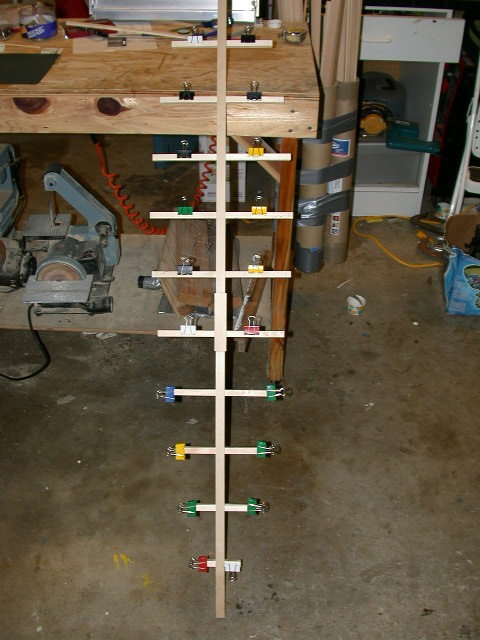
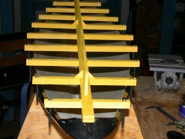
Now you have a structure with the beam pieces sandwiched. Roll it over so the base is now on top. Glue in ½” x ¼” Basswood to match the beam pieces out from the base (top). This double thickness will give stability and purchase for the screws. Center and glue onto the top a 3" x 1/4" x 48" to stiffen and straighten the centerline of the jig. Some equal triangle braces were made from 3/4" stock to support the stiffener. Place some kind of reference item over the bow end to mark the end of the jig to the hull bow as a stop.
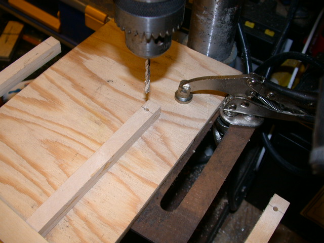
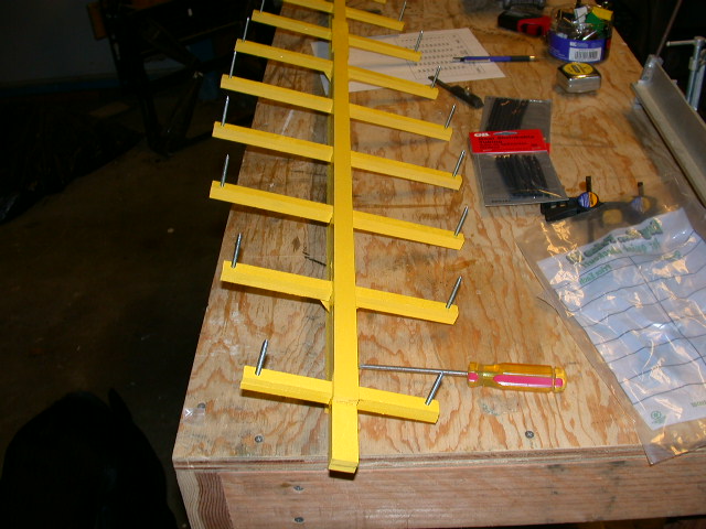
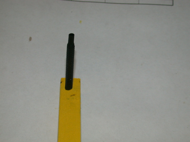
When you have a good cure, clean it up and paint it if you like. Drill the holes for the screws with a #23 or 5/32” bit. Insert the screws and install the shrink tube.
Now you can mark the location of your rib set up on the sides of the bottom piece where the rib slot will fit. When you install ribs into this slot, trim the gunwale flange end of the ribs equally and later sand the camber to fit.
What do you think? Cool, huh?
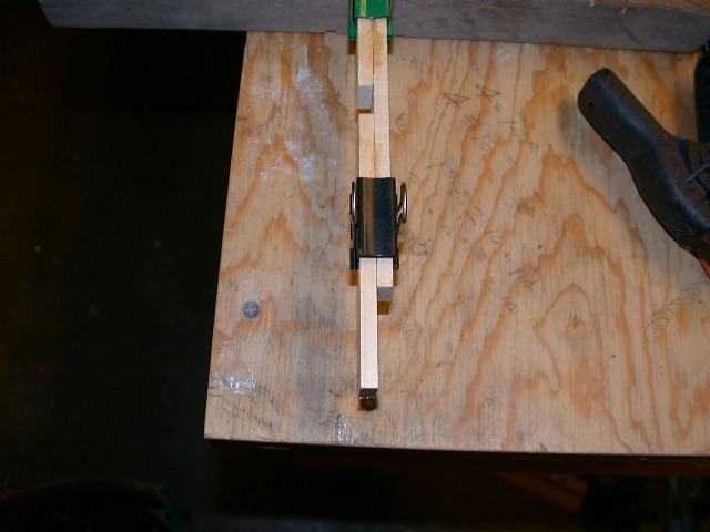
Note: This was the result of a check of the actual beam measurements after construction and installation of the screws and shrink tube. It will give you some idea that drilling is not a precision thing in most home shops. It was thought to be quite adequate here.
Also note that most calipers are 6" in length, at least the reasonably priced ones. Measure the longer beam widths from center to complete the check. When the jig was installed on a hull the screws were checked to make sure they were evenly spaced off the hull. This precaution is to catch that one side is not drilled differently than the other but still measures into specifications. It only stands to reason that if you have gone to the trouble to build this tool, make sure it is right and symmetrical. Enjoy...Oh, starboard stations 35 and 40 were re-sleeved with shrink tube to bring them into specification. It is thought that Vern drilled it while we were on break. The good news was that Murphy was not with him.
|