|
Phantom of the Bilge, Unmasked, July 2003
Phantom of
the Bilge, June 2003
Sheetline Travel Resolution, part 2, the RMG 280c with 7.2 turns, March 2002
Note: The
280c is no longer in production and is replaced with the 280DL, which is not a
hybrid but the long awaited SWxxx winch. These reports will be replaced when
this new winch is available in the shop... July 2003.
Sheetline Travel Resolution,
part 1, July 2001
Bow
Block Separation From Bulkhead
By Rick West, Delta MYC EC12 Racing Team
Most of
us would have headed for the hacksaw. Not Dave Brawner. During the construction
a DuBro 440 Rigging Coupler had been installed in Station 4 for mounting the
Pekabe block that would be the turning point for the winch line. A split ring
was used to secure the block to the coupler. In time the boat went into the
water and received enough sheet line stress that the ring gave way and the block
rebounded to the back of the boat. Set and Match, done deal. There is no
retrieval loop or anything, just a block in your hand and nothing headed for the
bow.
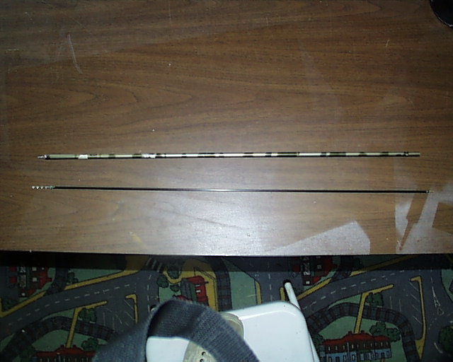
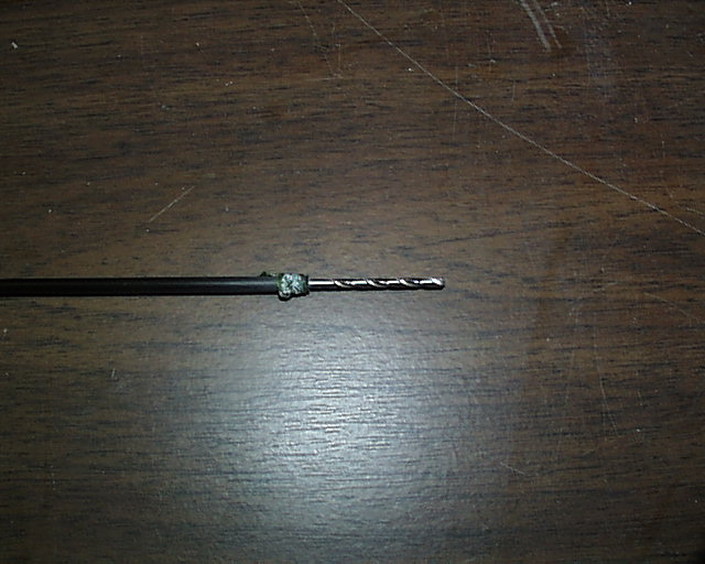
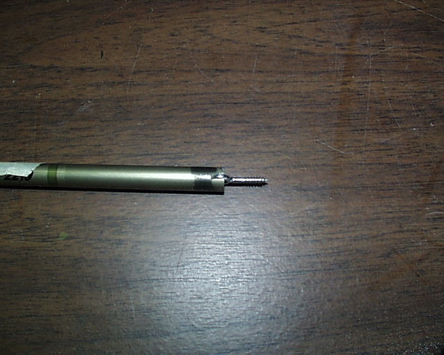
Dave's
idea caused a search of the shop for a small ID Carbon Fiber hollow rod. He then
matched a drill bit to it and a rod at the other end that would fit into the
chuck of a drill. He now matched an eye screw to the drill bit that would allow
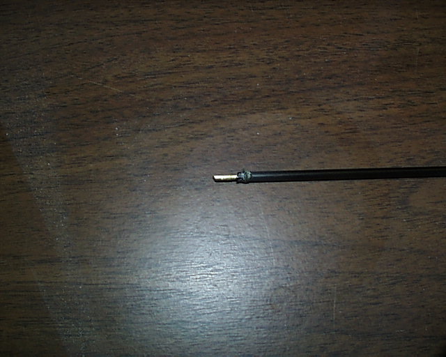
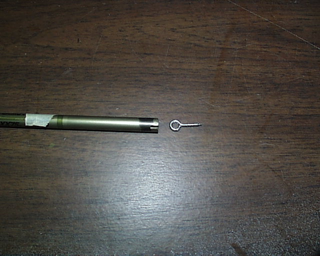
a secure threading of the screw. Then a slot was cut into the end of an arrow
shaft, with a wood insert, that would fit the eye screw. This fit would be tight
enough to not allow the screw to droop. With this floppy 30" fashioned bit,
he drilled a hole beside the failed mount on the bulkhead. He attached the lines
to the block, the horseshoe of the block to the eye screw and stuck it into
the slot on the arrow shaft. He then moved this forward and found the drilled
hole while viewing through a mirror and began to twist the shaft to screw the
eye into the bulkhead.
The lines
were untwisted and the boat was operational. Remember this, you may need it some
day.
EC12 Sheet Line
Travel
Resolution and the RMG Winch
(This is part of a series of discussions being prepared for the beginning
EC12 builder and sailor. These will be included with the Electronic Checklist
that will appear this winter (January 2002) on a new website for the EC12 class by Delta MYC.)
By Rick West, Delta MYC EC12 Racing Team,
August 2001
RMG is currently producing three Smartwinch models and several drum options
for each. The Smartwinch is a processor programmed 250-step motor to a drum,
either spooled or ramped. The processor is programmed by, and for, your radio
transmitter. During the process you can set the travel limits of the winch to
match your needs. Here is some information regarding winch terms as an aid in
the following presentation.
SW380 Winch – A 250-step motor with positioning accuracy within 3 to 5mm of
rotation. This winch is used in the EC12 but considered by many as torque
overkill.
SW280 Winch – Same as the SW380 but with less torque and a good match for
the EC12.
SW280c Winch – Same as the SW280 but with 1mm positioning accuracy.
SWXXX Winch – In development. A 500-step motor with positioning accuracy to
within 1mm. This winch is likely to have processor software programming to
provide exponential rotation that you can specify with your radio transmitter.
The standard drum provided with the winch package is not suitable for the
EC12. Optional drums offered are 32, 26 and 20mm in diameter and are provided as
single and dual spooled and one with ramping step-down design.
"Spooled" drums are where the line is wound upon itself during
rotation. Double spools are for dual lines. "Ramped" drums are like
worm gears where a single line travels through a series of spiral grooves to an
area where the line is ramped down to a smaller diameter section often called
the axle. This is called a step-down spiral drum. The Smartwinch can be
programmed to provide more than one turn on the axle. A review of the
RMG
website will give you the drawing presentation of these drums.
Motor "Step" is the incremental position movement the motor can
make by signal inputs through its complete rotational range.
Step "Positioning" is what makes the winch a servo as it will seek
a certain step position by signal inputs to the radio receiver. The accuracy of
this positioning is what gives the winch values of resolution.
All current production winches will produce about 5.5 revolutions of the
drum. The EC12 needs a minimum 16" of sheet line travel at the fairleads
(exit guides) to move the booms the full operational range. Therefore the size
of the drum is important when all you can get is 5.5 turns. A 26mm (1.02 inches)
constant diameter drum will produce around 449mm (17.5 inches) of sheet line
travel. However, there are several problems we would like to avoid with this
design of drum, poor resolution and too much speed.
The RMG winch can complete a full 5.5 turns in about 1.9 seconds, way to fast
for our liking and reasonable sailing control. It stands to reason also that
even small adjustments in the sail set will be competed in nanoseconds. While
the math states that the drum will rotate .022 turns per motor step, the reality
is that the radio transmitter does not have 250 controllable steps. The general
amount of stick control increments on most transmitters is around 26. For the
sake of discussion, lets say, this is 10 motor steps for each bumps of the
stick. If you play with the math this will come out to about .67 inches of sheet
line movement for each bump of the stick. That is not good resolution in line
travel while the winch is doing a good job. It also stands to reason that if a
26mm diameter is needed for programming 16 inches of line travel that the
smaller 20mm drum will not give us the amount of travel needed (345mm or 13.5
inches). Therefore, none of the RMG winch drums will work. "Well, don’t
give up yet, Vern."
So, what can be done? The approach was to attack the drum, to create a hybrid
drum that would do everything. Northwest EC12 boaters called on master craftsman
Maury Thoresen to produce a drum that will provide 16 inches of travel, slow the
winch down where the finer adjustments are made and provide good line resolution
where it counts, at close hauled, all in 5.5 turns of the winch. This was no
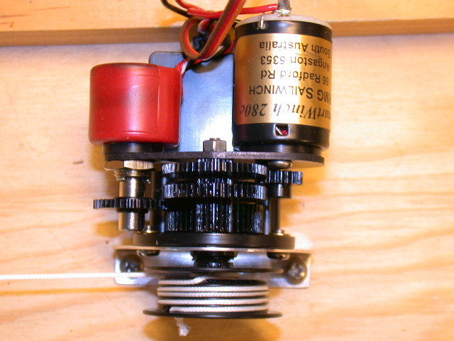
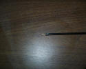
easy task. Maury came up with the tapered ramping step-down spiral drum. This
drum is shown here. This drum requires more than three dozen lathe sets during
manufacture and if we had to pay for the labor and amortized R&D, we would
not be able to afford one.
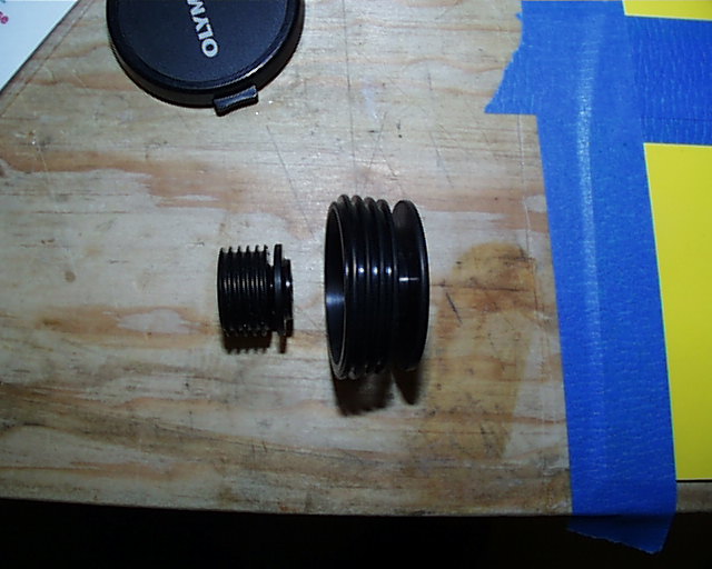
As you can see, the axle of the step-down portion (next to the winch mount)
is very small and then the line ramps up to ever increasing diameter grooves to
the end of the drum where the winch line is secured. As you start to sheet out
from closed hauled, the sheet line movement will be very small while on the axle
then start increasing as the line ramps up on the larger diameter grooves. This
causes the sails to move slowly at close-hauled and increase speed toward full
sheet out as it approaches that limit. Likewise, the sail movement will slow
considerably as you return near close-hauled. Meanwhile, the speed and
resolution of the winch motor is constant. It is Physics.
Why the line speed variations? It is said that good EC12 sailors will make
90% of their sail adjustments within 30 degree of close-hauled. The design of
the drum will vary the speed of the line travel as a function of drum diameter.
The slower the line speed relates to lesser diameter and hence less line travel
per input. This in turn becomes better resolution at the booms. The trade off is
that the speed is increased in the latter steps of full sheet, out where minor
adjustments are less likely to be made.
For several years this has been the best way to manage sheet line resolution
and in effect slow down the winch. But there were still the problems of winch
speed between steps and consideration for Maury. He is in his mid-eighties, a
good competitive sailor and working for us at minimum wage if not slave labor.
There are other possibilities and we can give this man a break.
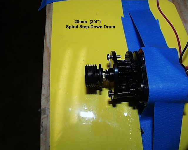
RMG will now modify the SW380 and SW280 Smartwinch (Not the SW280c) to
produce 11 turns through complete travel. This slows the travel time between
motor steps and allows us to use a smaller diameter drum. It will provide more
than 16 inches of sheet line travel and give us better line resolution. Now the
20mm step-down spiral drum will work and would be the one of choice.
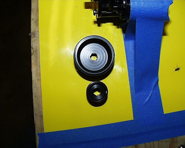
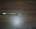
Note:
The 3/4" drum shown here is made by Ray Houtz. It is on loan for this
testing and photo session. The RMG drum will be similar with a flange on the
outer edge.


If the winch line is secured at the end of the outer groove and pointed
straight at the bow turning block with no line left on the drum, you will have
about 4.5 turns on the axle. Remembering, that one bump on the transmitter is
equal to 10 motor steps, then the 10mm (.39 inches) diameter axle will give you
just under 3/8" of line travel resolution. There are 5 turns on the 20mm
(.78 inches) grooves of the drum and the line travel resolution is .7 inches.
Running the numbers between the two diameters, your finest line travel
resolution will be in the first 30% of your boom movement from close-hauled.
Bingo!
The bumps on the transmitter stick are what we feel in the finger. With some
practice, testing showed that the winch could be moved 6 times to complete a
full turn. Some stock transmitters like the Ace, do not have these bumps and you
could do this easily once the stick was sleeved to make it rigid. Others have
modified the transmitter to eliminate the bumps. If you are that intense on the
stick you can cut the line resolution to around 3/16 of an inch.
This is good.
The line travel measurements above were made with the proportional radio.
Some computer programmed units can provide exponential movement. This
programming offers very small movement signals to a servo then increasing the
rate until full throw is achieved. With this type of transmitter (A Futaba 6XAS
was used here) you can reduce the number of motor step movement per bump of the
stick. At 75% maximum exponential rate the second bump of the stick, and first
to show movement, was 3/16 inches and 1/8" for the next three. (Why one
bump is skipped is not known here). There were 10 bumps in all for a full turn.
As was mentioned in the paragraph above, 6 turns were achieved in proportional.
This is very good resolution.
With the boat lying on its side, in a still room 20 feet away, you can only
tell it has moved is by the slight rattle of the sails. On the water you will
never see it, only sense it. You will, however, notice the change in
performance.
The rate can be programmed. You also have the ability to turn this function
off with a switch on the transmitter. While it may be desired to increase the
line travel resolution, the function is very useful with the rudder by dampening
deflections when in panic or having the jitters. They are less expensive than
the Ace Nautical Commander but are available only on 50 and 72 MHz frequencies.
A frequency conversion might be worthwhile.
You can slow the winch down if you want even more improvements. Disable the
low voltage winch shut off programming and run the winch with a 4.8v battery
rather than the normal 6 volts. You will then not be able to see the movement.
At Delta MYC, the Ozmun W-12 swing arm winch and the RMG Smartwinch are all
that have been tried. We cannot comment on the fine quality of other winches nor
their enhancement possibilities. It is hoped that this was helpful in your
pursuit to excellence.
Note: If you want the SW280 winch with 11 turns, you have to
ask for it. If
you want the 20mm step-down spiral drum, you have to ask for it. Sorry, the stop
watch could not be found to run full travel speed checks with the above
suggestions but it does take more time to complete the span.
Sheetline
Travel Resolution, part 2
The RMG 280c
Smartwinch geared for 7.2 turns and the 26mm SDS drum
The hybrid has arrived and it is not
a mutant. The road has been long and with many diversions but now comes a winch
system with real promise. It was mentioned in Part 1 that a form of this winch
was coming. What was not known at that time was that Rob Guyatt was also
preparing to offer drums specific to your needs and at a reasonable price. His
listening to the needs of the EC12 class, the services provided and the
excellent customer support offered by his company has given EC12 captains
confidence the product with smoothness in sheeting control, performance and the
sailing feel of a real racing yacht. You are going to like this system.
Please remember, from the previous
article, the prime concern here at DMYC is line resolution not the resolution of
the winch. There are two factors that separate the two; drum size and the
transmitter. It is the end result that we are interested in. That is, how does
the boom move when an input is made. That movement is line resolution.
The model 280c has provided another
factor that has made this system attractive. The "c" notes that this winch is
not like the standard 280 or its more powerful partner the 380. The positioning
accuracy has improved from 3mm to 1mm. It is amazing the difference this has
made to the smoothness of the winch. With intense concentration, you can almost
make the motor creep.


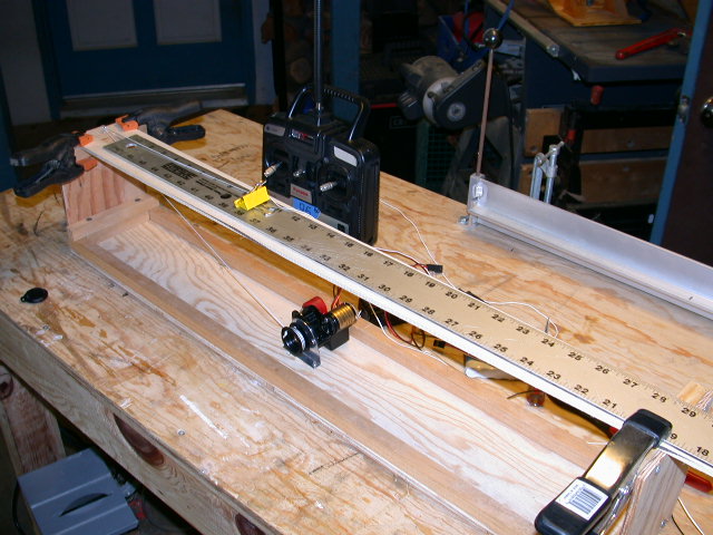
Testing: The Futaba Skysport and the
Ace Nautical Commander transmitters were used. The Ace is modified in that the
#1 stick has been sleeved with a brass tube to lessen flex of the stick and add
some feel. A 6v NiMH battery was used for all the testing and random use of a
4.8v battery produced the same resolution numbers, albeit slower and really not
any smoother. A jig was built to perform the test and a metal rule and stop
watch for the measuring. This was not a professional laboratory procedure but
one thought to simulate an actual installation and use on the water. Whereas,
several winches and drums were tested, a single removable 200# Spectra winch
line was prepared. The differences between this line and standard 80# Spectra or
Spiderwire would be minute if any.
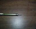
The test of the 7.2 winch was using a
26mm step-down spiral drum. The axle diameter of the drum is 10mm. This drum was
the perfect match for the EC12 and this winch. The drum has a single steep ramp
down from the larger diameter to the axle. The reverse is a single jump to the
larger part of the spool.
Speed: It is not important to us but
total rotation is 2.1 seconds. If you do not slam the stick to close haul and
use a bear away footed set at the leeward mark, a smooth motion to close hauled
then cracking the stick to foot a bit is within .1 of 5.3 seconds for the feel
and thumb used in this test. It was nice.
Sheetline Travel: Full length is 18
inches. This is a bit more than needed but will leave the builder with
flexibility in positioning the main boom at full sheet out.
Sheetline Resolution: As mentioned
above, intense concentration would creep the winch. The Futaba could accomplish
less than 1/8" movement. However, in the real world 1/8" and 3/16" was easily
obtained. This movement was consistent through the 3-1/2" of travel while on the
axle of the drum. Historically, this is where most of the adjustments at close
hauled are made and there is plenty of it. There was 1" of travel as the line
leaped to the 26mm spool. If this was an area of close reaching, the line enters
the ramp by bring the winch in a bit. Knowing this would cause nothing to be
missed.
Motion: This winch is very smooth. If
you move the stick with just applied pressure, the motor will begin to rotate in
that direction in a creeping motion. This movement cannot be seen at a short
distance only heard. This unit has not been used here in the water. However, it
is expected not to have the rig rattling starts and stops as the 11-turn model
with the 16:1 gear ratio.
The Ace transmitter did not fair as
well with the winch. The pot movement is jerky without even smoothness. Hence,
stick movements were not consistent with good line resolution. The Hitec Ranger
3 was not available at the time of testing but it is expected to do well with
this system. The Ranger has a very nice smooth stick movement.
Try it...you'll like it.
Phantom of the Bilge
Rick West, June 2003
This article could save you time,
anxiety and points. It is about a radio gear electronics problem that defied
reason and became a plaguing insidious and frustrating experience. Grab a drink
and settle in.
During the winter and spring of 2003,
the yellow Ribeiro #94 was re-decked
and refitted. The radio gear was removed from the ballast mounting to
a board. The winch was updated and the rudder servo replaced for one with a
larger torque value. All boat radio gear was disassembled and coated with
Aeroplate. The boat was then taken to the East Coast for the Jacksonville
regatta the first of March. This would be 94's fourth racing campaign.
The boat performed well and no line
or shroud failures occurring. However, on two occasions at the far windward mark
across the pond, the boat did not respond during the rounding. It was momentary
and was not noticed by anyone but the skipper. It was a moment when rudder and
sheets did not respond to a slight change and then to a greater one in panic.
Then all was normal. Puzzling, then it happen again at the same location several
heats later.
The next event was the Champions
Regatta in Charleston the third week of March. The incidents were not out of
mind and the boat was sailed with all gear inspected and tested the day before
the event. All was well.
The first three heats went without a
glitch and the long awaited event was under way. During the pre-start dance of
the fourth heat, 94 suddenly stopped answering signals from the transmitter. The
rudder and winch were dead. The boat drifted to shore away from the racing and
brought onto the grass. Everything worked!
The bilge was checked for water, there
was none.
The solder connections around the
power switch checked okay.
Plugs into the receiver and battery
checked okay.
The transmitter antenna was secure
and the Futaba 6X programming okay.
The boat was placed back in the water
away from the race course and it would not respond. The boat was recovered and
moved to the pit area and placed in its cradle on the worktable. While pondering
the events the boat was inspected over and over. Everything was working on the
table.
The RD was advised the boat was ready
for the fifth heat. She sailed to the line and quit again. This delayed the
start till the boat was recovered and moved back to the pit area again. The boat
would respond on the table. The receiver was changed and the boat put in the
water only to have it quit again. A spare transmitter was brought out, the
primary crystal installed and it would not respond.
She was recovered and this time she
would not respond on the table. Everything was thought out in consultation with
others around. The battery was checked for voltage at 6.5v. It was changed for
one with 6.9v. The boat started working. The RD was advised and the boat was put
in the water for the sixth heat. She never made it to the line.
This time, when the boat was placed
on the table, the rudder servo was twitching and would respond with jerky
movements when signaled by the transmitter. The winch would not move during this
time. The rudder servo was unplugged from the receiver to check for corrosion (a
wild guess) and the winch moved as the stick had been left in a different spot
than before. AHA! There was something wrong with the brand new Hitec 645MG
servo.
By this time 94 had missed three
heats in the most elite event of the year and the skipper was not in a good
frame of mind. This was a spectator event and 94 was withdrawn for the day to
watch the event.
Saturday night the servo was replaced
with a lower torque S148 carried as a spare and the boat responded well on the
table. Because of the Jacksonville history and the symptoms now displayed there
appeared to be a radio connection problem with the boat. The greatest puzzle was
lack of control in the water but to return on shore. It was not till the servo
starting twitching that any recognizable sign or pattern was realized.
The boat was put in the water Sunday
morning to race with the group. It seemed to respond fine but the event was
called after an hour of false starts due to no air. It is now suspected that one
of two things occurred:
-
The signal function in the servo
failed under load and corrupted the receiver when not close to the transmitter.
-
There was an electrical short in the
servo when under load that caused the voltage to drop below 3.5, shutting down
the winch.
Whatever is not known but the
symptoms are. The servo would have been thrown out of the airplane on the way
back to California had not the owner been sucked out with it. It may be sent
back for analysis after the season.
The Beat
Goes On
Returning to Charleston for the
Wisteria Cup in May, the S148 servo was replaced with a new 100 ounce torque
Futaba S9303. There were five more incidences with the same symptoms, four at
the far leeward mark on the outside (the fartherest point on the course) and
once at the finish. Control was re-established by holding the transmitter up
high. Whereas 94 lead the regatta from the start and eventually won, these were
nerve racking moments as a flood of thoughts came forth. Discussions on shore
between heats all pointed to signal strengths when none should be present if all
is normal. Hence, this pointed the the TX or the RX. However, none were changed
awaiting a total shutdown. It never came.
Friday afternoon the Shamrock V
J-Class boat #94 was demonstrated to those gathering for the Century Cup at
Elon. While they played the EC12 #94 was readied and put in the water. After
about an hour of mock racing with the group the boat failed to respond and
drifted to the far side of the pond. When walking around the lake to retrieve
the boat, she began to respond when nearer, and was sailed around the edge back
to the control area. This was every indication of a signal strength problem.
Many suggestions ensued. The RX was changed. The TX was changed. The antennas
were changed. Then it was thought that the TX crystal was no longer matched so
both were changed. What was noticed was that the rudder was moving slower than
normal when signaled. Whereas, this could also point to the TX exponential
control programming, it re-enforced a radio malfunction.
Through all the changes the boat
would function on shore and in the water only to quit somewhere in the race.
When the crystals were changed all became normal for about 30 to 45 minutes of
mock racing ending the day.
The boat continued to function
normally all Saturday morning and then failed at a start after lunch. When back
on the table everything was normal. There were plenty of suggestions but all had
been tried. It was hard to suspect the rudder servo again as it had just been
installed. The boat was put back in the water only to fail in another heat for a
DNF. Now, she was put on the table and the new 9303 was removed and replaced
with the standby S148. Another heat had been missed.
The boat performed normally the rest
of the day and to the finish on Sunday. She sailed well with no hint of anomaly.
Can you believe this?
Meanwhile, on Sunday, Dick Gerry's
1096 started sailing in circles. When recovered to shore it operated normally.
Every time she was put in the water it would quit. The Phantom had struck again
and Dick retired knowing that it was useless to try even when the boat appeared
to be okay. The word was going around that 94 had released a rudder servo virus.
Considering the odds, lottery ticket purchases were in order.
Is the Phantom gone? At Mystic, 94
will have another new Hitec 645MG servo installed. Stay tuned.
Phantom of the Bilge, Unmasked
Rick West, July 2003
When was the last
time you read the RMG Smartwinch manual? When was the last time you studied
the electrical properties of the winch? Did you even pay any attention to a
diagram feature called the “Voltage Regulator.” Have you read Section 6 and
understand the function? This electrical device lies within the winch
controller but it is not the Phantom of the Bilge. It carries the key that
unlocks the mask.
There was nothing
wrong with the voltage regulator or the winch. There was nothing wrong with
the rudder servo. There was nothing wrong with the transmitter or the receiver
or even the crystal alignment. There was nothing wrong with the power switch
or the jib trim servo. The long carbon fiber rod link from rudder servo to the
tiller did not disturb the electromagnetic function of the equipment board.
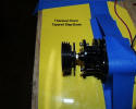
The Phantom of the Bilge was this Dummy and the wiring of the board. It is the
same wiring used since day one in EC12s, diagramed on this and the original
building website and in all boats that have come out of the DMYC shop. It was
this Dummy, who installed another high torque servo and released an insidious
and frustrating chain of event failures that defied reason by hiding the
cause. Additionally, the failures were random in when they would happen,
sometimes partial to the rudder servo and others a total shutdown of the
onboard radio system.
Let me state it again. If you have read Phantom of the Bilge, know this; there
was nothing wrong with any of the RC gear. The wiring of the equipment board
was wrong based on a known device in the winch controller. If you have wired
your boat with the winch ribbon wire plugged into the receiver and supplying
power to all the RC gear onboard, you are headed for a fall.
Sections 2, 6, 7
and 8 tell the story of what “Smart” is in the RMG winch. Here is a
clearer version and the reason for changes to the electrical wiring in the
Electronics section of this website:
Section 6 explains that a voltage regulator provides up to ONE AMP to the
winch controller circuit, the RX and the rudder servo. Please NOTE it did not
say anything about a trim or twitcher servo. This section also refers to
“Figure 1” where you can see the wiring of the voltage regulator. Here you
will see a three wire ribbon from the winch that will plug into the RX slot
for the stick position that you use to control the sheets. The brown and red
wires carry power to the RX which is also distributed to the other servos
plugged into the RX. The orange wire is the signal lead from the RX to the
winch via instructions from transmitter signals. Okay so far?
Also note in this diagram that the voltage regulator connects into the boat
battery leads before it gets to the winch controller (MCU). The regulator then
connects into the winch ribbon wire after the controller. It is through this
path within the controller that flows up to ONE AMP for all the radio gear
aboard except the winch motor. If you add up the maximum power usage of the RX
and all the servos that you are using, could be three, and if it totals close
to or over ONE AMP you are in deep doodoo. You have added them up, right?
Sure, just like this Dummy did.
Rob Guyatt, of
RMG, has provided all the information in the manual and the flow is
reasonable. Generally, all of this would not be connected without study in
re-reads. Some of us might read instructions and manuals,
some, much less study
them.
Why has this not
been a problem? Well, it might have been and the source not known. Those that
knew, through study or experience, may not have been able to pass it on or
thought everyone else knew. This site is one of few, if not the only source of
such experiences, for the EC12 community.
Many, like this
Dummy, have been using low torque servos for the rudder and twitcher, like the
S3003s or S148. The trim servo has to be high torque to hold the pressure on
the sail. However, it would not be until all were in use at the same time
could the ONE AMP limit be reached. Once you upgrade to a high torque servo
for the rudder, like this Dummy did, it was the story of a house of cards.
This is likely to happen first at a leeward mark rounding. The winch is
hauling in the sheets, the rudder is active and the jib trim servo is trimming
in and then holding the load of wind pressure for the beat. Then, as the
voltage in the battery slowly drops through time, which is normal, less and
less flows through the regulator as the winch demands its normal draw. Now
failures start to occur at the start like for this Dummy.
So, to continue…
Moving on to Section 7 we get sucked in with the words “best” and “simplest”
and read no further besides, Section 7 is titled “Standard Connections.” We
certainly do not want to be “Alternate Connections,” which is the title of
Section 8, right? Well, that is where the EC12 should be and wired
accordingly.
The section is very clear as to why you would want this wiring had we read it
or, even in reading, understood the implications. Rob states that if you use
more than a winch and rudder aboard it is advisable to bypass the voltage
regulator as there MAY NOT be enough power left for other things.
A study of Figure 4 shows how this BYPASS is done; forget the extra switch, it
is not needed. Power is now routed from the “ON” side of the boat power switch
to the winch, as usual, but also via a servo extension ribbon wire to the
battery slot in the RX. Now, and this is important, the red wire on the winch
ribbon leading to the RX MUST be disconnected. This prevents TWO power sources
to the RX. This bypasses the voltage regulator and provides full voltage and
far more than one amp to the RX and on to the rest of the onboard RC gear.
This is the correct way to wire an EC12 to cover all power needs now and in
the future with additions or higher torque servos as optioned.
Now, if you are
concerned that there will not be enough voltage to run the winch during high
draw periods (like at the leeward mark), two batteries can be installed; one
for the RX and RC gear and one for the winch. The Electronics section of the
website will now have both diagrams. Some EC12 owners are running two
batteries, however, this should not be needed with timed battery changes at a
regatta, The RMG winch will function down to 3.5 volts where the controller
will shutdown the operation of the winch.
Here is a link
within the building site for the wiring diagrams.
The correct
wiring of the RMG
Okay, that is it
but one more note that may be of interest to those who have had rudder servo
failures, meaning the servo will not work on the bench apart from the system.
This Dummy’s Hitec 645MG servo in the Phantom story will not work on the
bench. Such high torque coreless servos are known to need a high draw to get
started. Amplifier devices are used in the circuits to provide these spikes.
At this writing it is not known what damage may be caused to these amplifiers
due to an under current condition in the circuit. Without these the servo will
not work. If this has happened, the root cause may have been in the wiring and
not just a servo failure.
Good sailing,
fair winds and read the instructions!
|