Last update,
August 21, 2001
Building shown in this section is for reference in the Classic Build. Some links may no longer have a source and suppliers may not exist...Rick West, December 2009
The Twitcher Servo
Parts:
Futaba S148 or S3003 servo. Should be included in your radio system. If not, Servo City
.064 aluminum strips, your stock.
.032 aluminum sheet, Online Metals
6-32 SS cap machine screws, 3/8", (4), hardware store, Small Parts.
4-40 SS Phillips machine screw, 3/8", Stock Item
4-40 SS Nylock nuts, Stock Item
#4 SS washers, Stock Item
#2 sheet metal screw, 1/4" round head, (2), Stock Item
Tools:
Phillips screwdriver.
Pliers or nut driver.
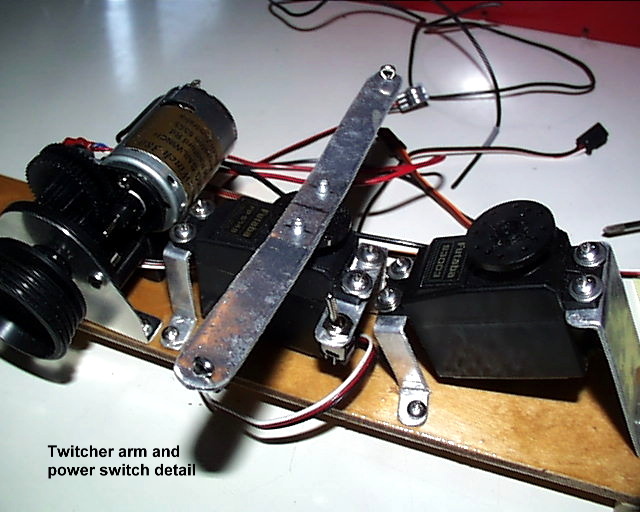
A strong servo is not needed for this device. The jib should be in a near neutral state when the Twitcher is activated. We do not set it up to be held in place, only thrown to the side desired and let the wind hold it in place. Our reasoning is that if the wind will not hold it there, then maybe it does not need to be there. Besides, forgetting to release the Twitcher rounding the leeward mark will cause some confusion and personal recriminations. Therefore, the left horizontal stick channel is used for Twitcher control.
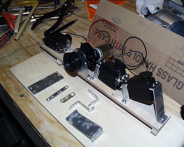
Make two "Z" mounting brackets from your stock of aluminum strips and drill the 3 holes needed for the 4-40 screws. These will be the "Z" shape. Note that the servo shaft for the arm is aft. Mount one bracket forward and so to be on the port side.
Cut one of the aluminum strips to 6 inches. Mark the center and drill a hole that will allow you to access the screw that holds the control wheel to the servo. Then drill smaller holes to screw the arm to the wheel and to attach the Twitcher lines on the end. Mount the arm to the wheel with #2 sheet metal screws. The wheel mentioned here is the stock wheel that comes with the servo.
The lines are described in the Lines Section and can be added at the very end of the boat’s assembly. Put this piece of equipment away till needed.
Note: The center hole is not shown here as it is a modification. Likewise, it was found that the cotter pins were not needed on the ends to attach the lines. The lines are not under stress and fraying should not be a constant problem. Likewise, the power switch has been moved to the rudder servo.
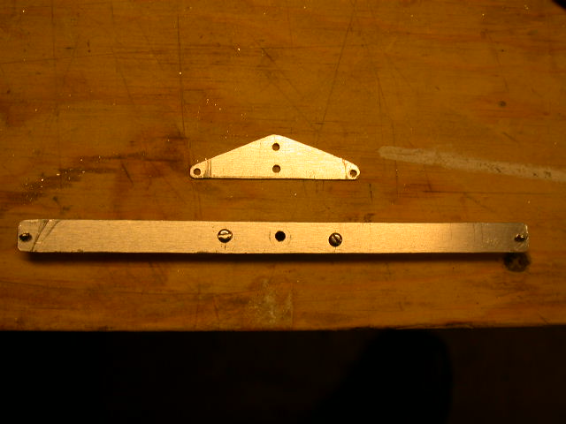
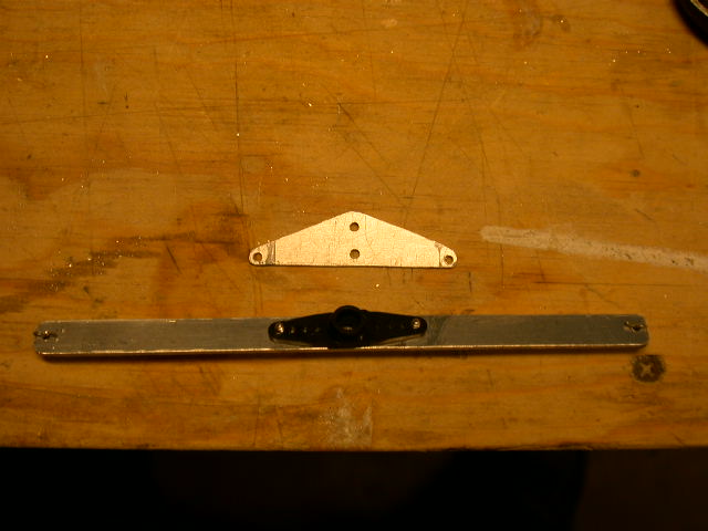
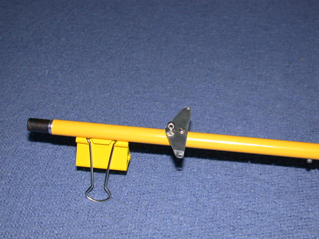
The flange is fashioned from .032 aluminum sheet, 2" by 5/8" and drilled with a #44 bit. All the edges are filed for smoothness. Put this away till needed.