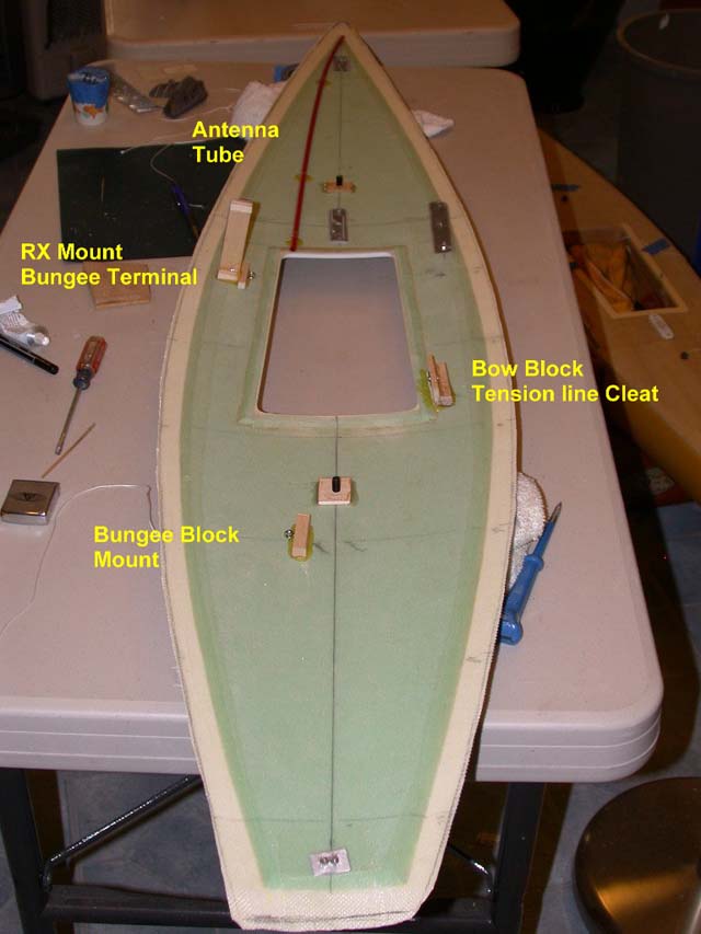
Antenna Tube
![]()
![]()
![]()
![]()
![]()
|
Antenna Tube
|
|
Last update, December 17, 2007
Parts: 9 gauge Teflon tubing, #STT-9, Small Parts.
Tools: Duct tape Epoxy
The presentation here is for antennas on radios in the 75, 50 and 26/27 MHz bands using crystal controlled frequencies in the transmitter and receiver. These antennas were long and required some 20 inches to deploy but could be used inside the hull. Tubing was used to route and protect them.
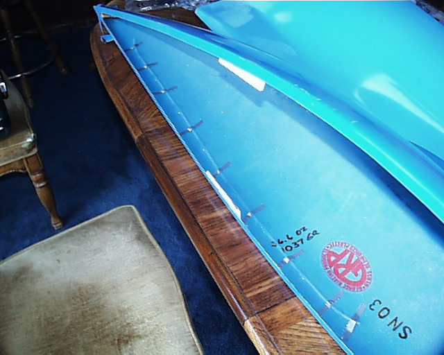
On the Hull This tube has worked well for us in the past. It provides a secure location away from the electrical functions with easy access. It is easy to thread when changing receivers or just removing them to another boat.
The tube is taped to the hull starting at around station 33 from the bow to a few inches short of station 4. It can be routed on either side depending on preference of wiring. Be careful not to kink the tube as it will restrict threading the antenna. Also be sure the tube is low enough to clear the ribs for the deck structure when they are installed. As opposed to the photos here, it is suggested that the aft end of the tube be curved down so the starting point is several inches lower in the hull. It is thought that this will make it easier to see the end of the tube when starting the antenna into the end. Currently, we are doing this by Braille.
Lay the hull on its side so the epoxy will not run. Place a bit of glue on each side of the tube then bridge it over forming a single bond. Do as many of these as you think are needed. Let it cure overnight. The antenna is inserted into the tube and pushed till all the slack is taken. The end of the antenna will hang out the bow end of the tube by a few inches.
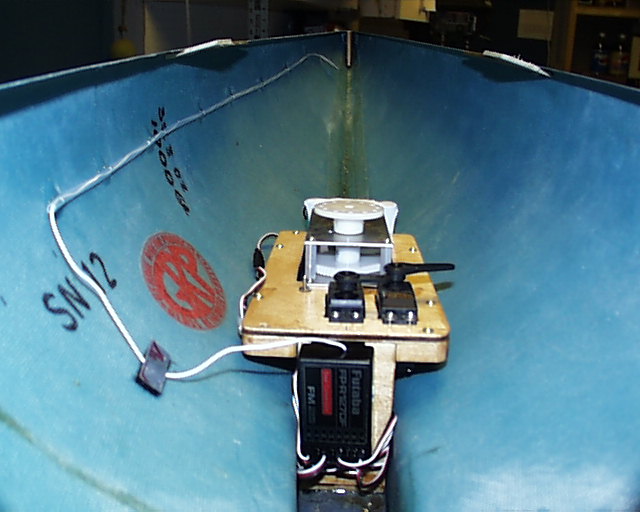
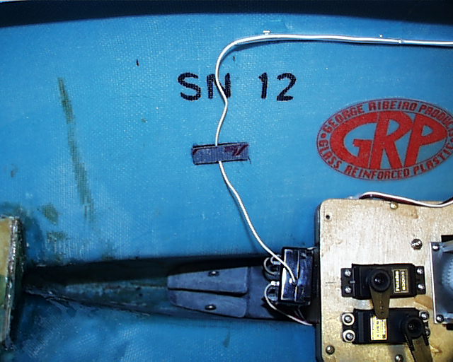
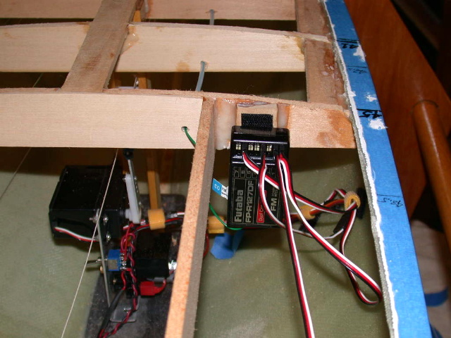
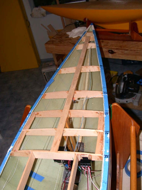
In the Ribs During a recent J class boat project the antenna tube was placed through the ribs of the foredeck sub structure. This innovation was used to mitigate any problems with reception as mentioned in red above. This positioning also gets the antenna away from power leads around the electronics and the receiver. In concert with this thought the radio receiver was placed on Velcro at a mount on the rib at the forward hatch area where the antenna tube begins. This position would get it out of the rain and any water that might be in the hull and very accessible.
The photos here are of a Shamrock J class but the construction is similar to the EC12 and show these positions. It is easy to do and very accessible. The RX position has been changed on all the EC12's here and this antenna routing will be done with new constructions.
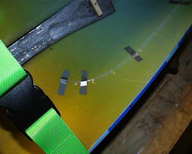
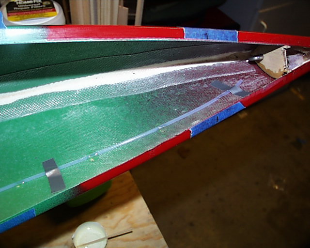
The Molded Deck When the molded deck arrive the same process of thought was carried forward. The RX was mounted under the deck on the starboard side with the antenna holder glued to the underside of the deck. This can be seen by the red tube. This was simple process and part of setting up the deck before installation.
Spread Spectrum When this radio 2.4GHz band hit the market it produced a totally different property to radio use and function. The antennal was much smaller and could be incorporated on the in hull radio board its self. This can be seen in the System Board section of the Electronic Checklist.
|