Structured Deck
![]()
![]()
![]()
![]()
![]()
|
Structured Deck
|
|
|
Last update, December 20, 2002 Building shown in this section is for reference in the Classic Build. Some links may no longer have a source and suppliers may not exist...Rick West, December 2009
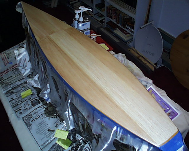
The Structured Deck
This page and the sub-sections to the left will take you through the complete decking process. This process is for a structured deck with ribs, balsa sheet covering and a resin hard finish. The EC will guide you through each step in the order needed. Please do not begin this process until the EC directs you. The process is designed so there will be stopping places for another day. Settle in, the total process is long.
Measuring And Marking The Hull
Throughout the building process there will be times for measuring. As you move about the tasks to the day the deck cover goes on, the knowledge of where things will be can give you a vision of the completed boat at various stages. Measurements give order to the project then if you care to fudge a bit here and there, you know from where to fudge. It is convenient to have these marks so you do not have to repeat measurements and then to measure from there.
All measurements are from the bow of the hull along the centerline. Measured marks are called stations. Marks along the centerline are transferred to the beam edge of the hull on the molded flange. This gives a square and perpendicular symmetry to the project.
Class specifications dictate beam widths to the hull at stations every 5" from the bow to the transom. These specifications are generous with a ¼" plus or minus leeway. It is easy to move one of these hulls during construction so always be conscious of this. We at DMYC choose to be dead center with these specifications, not as a matter of perfection, but to rely on all other measurements for positions that will produce consistent waterlines at maximum ballast with each boat built. It is like a child’s blankie at night.
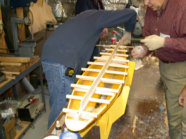
Those that build a lot of boats have a jig for this purpose. It is shown here for your information. You do not need one. But if you are a craftsman and there are a lot of EC12 people in your area, it would be convenient to share one. The Rinehart Deck Jig, shown above, is linked here to a construction page for a weekend project. Should you use such a tool the marking below will not be needed.
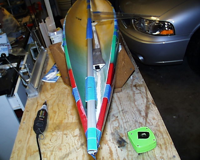
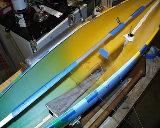
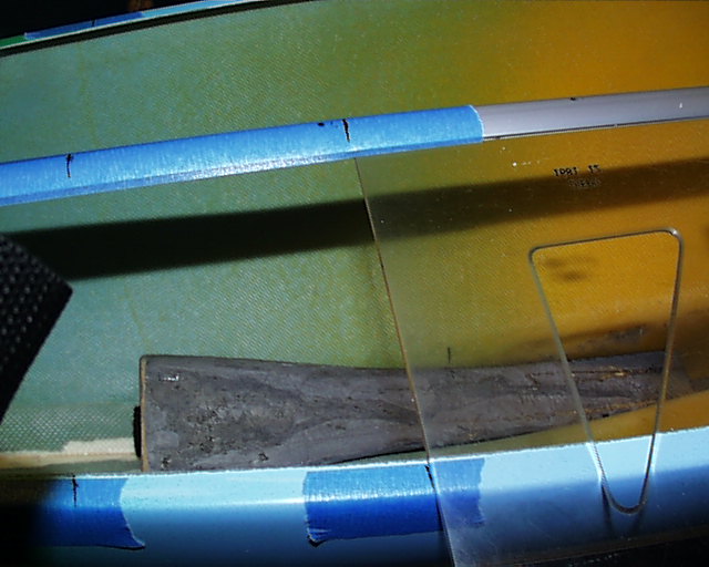
Marking Slip the ballast into the hull and settle it into its comfortable fit. Lay a five-foot piece of tape on the side of a Goldspar mast. This is to provide a marking surface. Measure from one end and make a mark at the following places: In inches, 10, 15, 20, 25, 30, 35, 40 and 45. Center the mast on the bow and transom and tape it down. Make sure the edge of the mast is flush with the bow. Lay the right triangle against the mast and mark the hull flange on both sides of these station numbers. You might like to place tape on the gunwale flange for marking. If you do, do not run the tape over the edge on the inside. Try not to move the mast in this process. Scribe the station numbers on the flange mark. These will be the beam specification checkpoints.
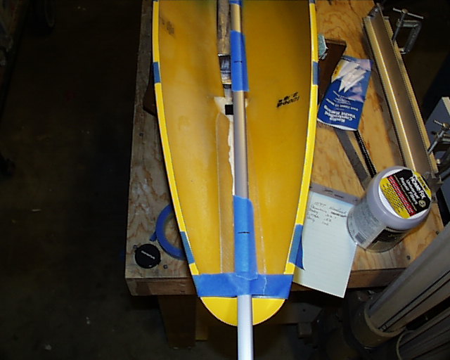
Now measure, maybe marking with a red pen, and follow the same process for stations: 3.5, 6, 8, 20-3/4, 24, 25-1/2, 27-1/2, 38-1/2, 45 and 55. These will be the rib and mast positions.
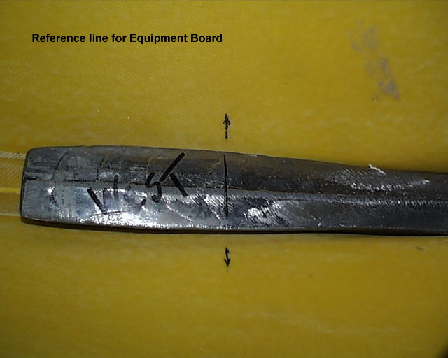
At the 25-1/2" mark, drop a plum line and transfer that mark to the ballast. Draw a square line across the ballast and mark the hull on one side as a continuation of that line. This process does several things, it allows you to insert the ballast to the same spot, position the RMG equipment board or swing arm board and mark the base of the compression strut.
You are done with the marking. Remove the mast, clean the tape off and put it away. Regardless of what equipment board you will use, it is suggested that the mast position, centered on the line of the ballast marked above, be dimpled with a drill and 3/8" bit. This will receive and stabilize the base of the removable compression strut.
That’s it! The centerline of the king plank will be marked later in the decking process.
|