Last update, December 15, 2002
Building shown in this section is for reference in the Classic Build. Some links may no longer have a source and suppliers may not exist...Rick West, December 2009
Installation of the Equipment Board
and
The Radio System Receiver
Parts:
The completed and assembled equipment board
4-40 SS Phillips machine screws, ½" pan head, Stock Item
Radio system and charged batteries.
Tools:
Screwdriver
Nylon ties
Wire cutters
RMG Winch Board
Install the assembled equipment board. You have most likely been through the drill during the construction of the board and assembly of the equipment so, this is no big deal. Two screws and you are done but read this through first.
At DMYC the receiver is installed on the hull under the gunwale outboard of the hatch, generally to starboard or wherever the antenna tube is located. This is secured with Velcro and the antenna fed into its tube. Servo extension wires are added to the trim servo and the winch so the receiver can reach into the area shown here. You can use a piece of blue tape to hold the antenna up away from the servo wires. Lighten up, its okay, this is not a boat or fashion show.
You can put the RX anywhere really. The considerations are rain, water in the hull and accessibility.
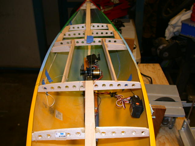
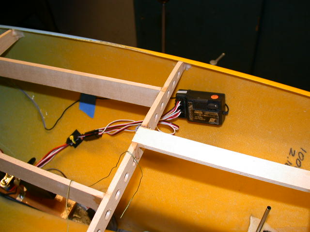
Before getting into all this remove the screw and drum from the winch. We do not use the screw to hold the drum on the winch. It is pretty snug and the winch angle will not pull the drum off the axle. This will simplify many of your maintenance tasks. Remove the arms from the trim and rudder servos if you have not adjusted them before. Organize the servo wires neatly with nylon ties and plug the equipment into the receiver. Check your radio system manual as to where each servo will be connected. If you have forgotten the layout, it goes like this: winch to the throttle channel, rudder to the aileron channel and the jib trim and twitcher to whatever you control channel you have available in your system.
Lay the board on the ballast and connect a battery. Turn on the TX and then the boat power switch. You should get one beep from the winch just like the last time you played with it.
One beep is good.
If hear a series of tones and then three rising ones, the winch is not getting signals from the receiver. Double check your wiring.
If you hear nothing, the winch is not getting power.
If you have not programmed the winch to its full turn capability, do so now. The programming checklist printed here is a more clear and understanding procedure than that provided by RMG in their blue manual. It precludes any missed steps and provides some clues as to why you are doing what you do. You might study the calibration checklist as the winch talks to you. It lets you know that it understands where it is as you move through the process. Note those items in green.
Note: This programming is for full turns. The winch will be reprogrammed during the Pre-Tune to the full sheet out position you will need. The two points are different in that you may not need the full turn capability of the winch.
The modified 280 will do 11 turns and the 380 and unmodified 280 will do 5.5 turns. The 280DL with the new gearbox will do 7.2 turns. The latter is recommended.
You may have done this when the board was assembled. Double check it now. Move the jib trim to full out. Place the arm (with the block installed, Right?) on the servo so that it will point to a place just barely forward of the jib exit guide. Bring the trim full in and it should now be around 90 degrees to the exit guide. Install the arm screw to secure it there.
Make sure the rudder trim on the TX is centered and install a one inch arm 90 degrees to the rudder shaft and pointing to starboard. Secure it with a screw.
When you are satisfied that everything is working and adjusted, insert the final screws to install the board in the boat.