Install Structure
![]()
![]()
![]()
![]()
![]()
![]()
![]()
![]()
|
Install Structure
|
|
Last update, December 20, 2002
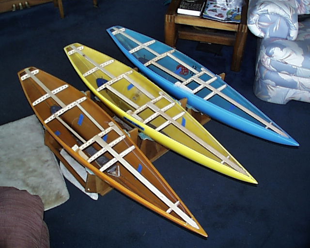
The Supporting Structure For The Deck
This section will cover the installation of the structure that will support the balsa deck and its gear. Measuring is a big deal here so if you have not marked the hull, please do so now.
This is also an area of changing design as other thoughts have come from certain needs. The foredeck is the area of greatest change as there appears to be a need to open the king plank for the possibility of entering the hull around station 4 for repairs. This design change also requires re-strengthening the jib rack support. In March of 2002 the foredeck was redesigned to reflect the new thinking. The Blueprint has provided the drawings for this design change and you will see it here as well. Because of file photos you will see a bit of the old and new.
Some Important Considerations Station 3.5 is the king pin of the sheet line system on this yacht. The bow turning block is located here and all sheeting control is routed through this block. A failure that renders the bow turning block ineffective can be catastrophic. It is not reachable without a major effort. Failures to this system would most likely end the day at a regatta.
There are currently two design thoughts, the hard mounted block and the line secured block. Neither is the end design solution to past problems but understanding the failures has caused builders to pause and take some time during preparations to installing a turning block. The change began in 2001 and other innovations appeared in 2002 and are listed below.
Station 3.5 means 3-1/2" from the bow. There really is no magic in this number as long as it is not greater than four. Station 3.5 has come to mean the secure bow location for the turning block. As you move forward in locations, the prime consideration is the elevation of the block due to the rise of the keel. Make sure that the winch line traveling to the sheets from the bow turning block is below the deck structure and free of friction. If it touches anything, it will fray. At DMYC we place the exit guide (fairlead) for the jib at station 22. You want to make sure that there will be at least 16-1/2" between the end of the block and the fairlead. This is the line travel needed for full sheeting with the DMYC station locations for the main and jib exit guides and boom guides.
Item 1:
Item 4:
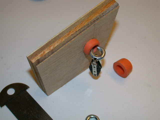
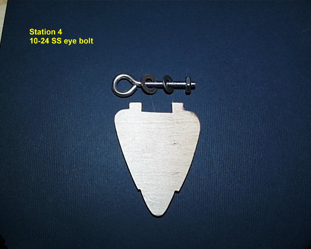
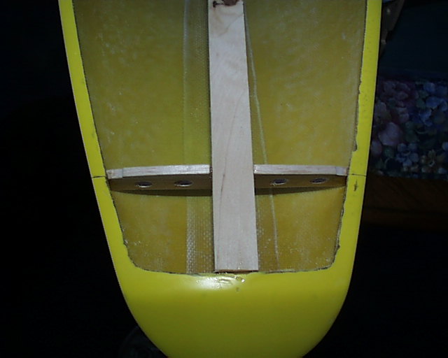
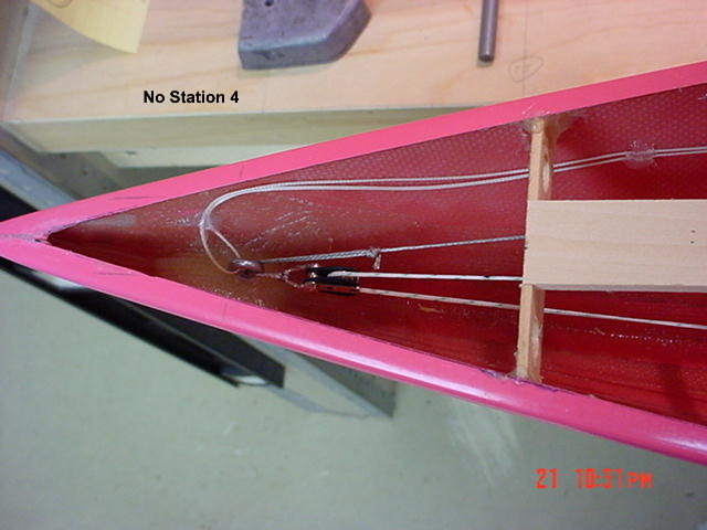
Install The Bulkhead Item 1: The line secured block system with a retrieval line requires a good quality eye bolt of brass or stainless steel is needed. It must be uncoated. The consensus is that the interior of the eye, where the line will pass, needs to be smoothed and highly polished to prevent line frays. Builders are now moving to larger eye screws and bolts to provide more surface, greater radius, for the line passing through.
The template on the Blueprint is approximant. Depending on the location, some trimming will be needed to match the fit and get the horns level with the flange. The inset for the king plank will need adjusting. Spend some time here as a good fit will add to a secure bonding of this bulkhead.
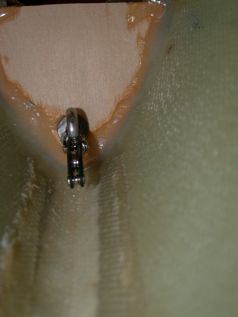
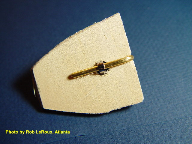
The bulkhead is pilot drilled 1-1/2" down from the flange for the eye bolt. The threads of the bolt are cut to 1/2" and cleaned for the nut. Secure the bolt with two washers and the nut. Align the eye so the loop closure is at the top. Place a bit of clear silicon at the end of the threads to prevent loosening. Allow this to set up and then install the bulkhead and glue it to the hull with thickened epoxy resin. Make sure no glue is anywhere around the eyelet. Allow this to cure.
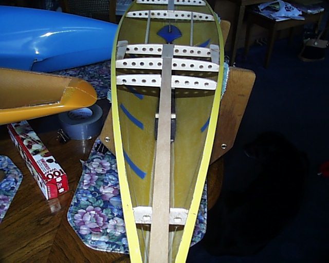
The photos here were during a process when the king plank extended to the bow. That is no longer done as the king plank ends at station 6 leaving the bow area open.
The photos here are those of a line secured block system as originally designed and published in the EC12 Manuals. This design provides a separate line for retrieval of the block. This line is not needed and only adds congestion at the eye bolt.
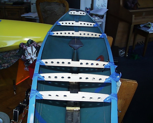
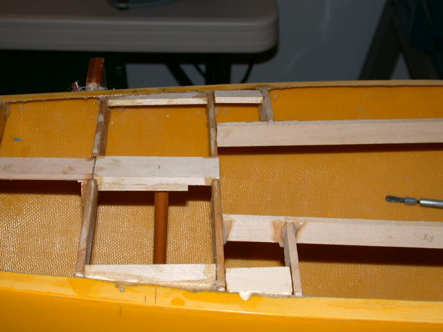
Temporarily install stations 20.75, 27.5, 38.5 and 45 stringers with tape. Run pieces of tape across the beam of the hull to make sure the hull is compressed against the stringers. Now check the beam measurements against the class rules specifications at station 20, 30, 40 and 45. We make an effort to be within 1/16" of the specified beam. You are allowed ¼" leeway either side, however, ballasting to meet the waterline restrictions in the rules will change if the hull is broad or narrow with respects to the listed beam measurements. We choose to be in the middle and our tank test numbers reflect that. The stringers measurements here are to put you in the middle of that range. Adjust the stringers if needed. When satisfied, remove the stringers and tape. Did you clean your hull in a previous section?
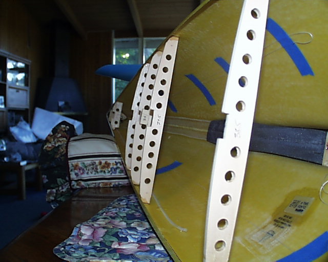
There are many ways to glue in the ribs. The above photos show three of ours. One is to loop tape under the rib and then over the hull flange. The other is to do one side at a time by blocking the keel level on its side with books. The third is to use bar clamps and tack the ribs with glue till cured. Some have told me they CA glue the ribs in position and then add the epoxy. Any of these methods allow all the ribs to be set in place, on station, to begin gluing.
Check the alignment one more time. Mix a batch of epoxy resin into a thick tooth paste with a filler. Fill a syringe and go to work. A gloved finger works good under the gunwale flange. Allow to cure.
The centerline king planks are 3/16" by 3/4" basswood. Cut to fit the forward plank, bow through station 24. You can bevel it to fit under the flange at the bow if you use this piece. Cut to fit the aft plank and do bevel this under the transom flange. This is a high stress area. Check the fit and sand or shim as needed. Mix a small batch of pasty epoxy and glue them in.
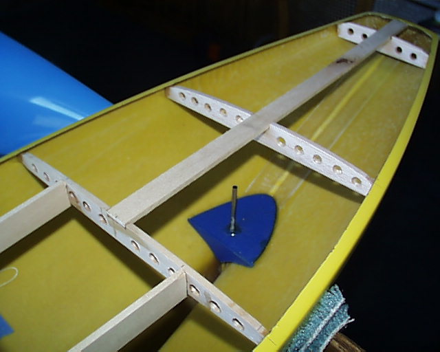
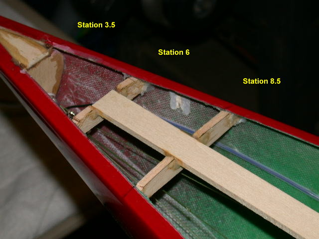
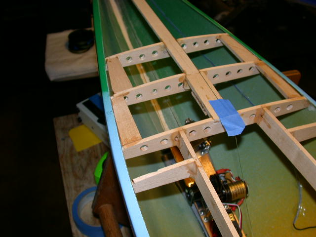
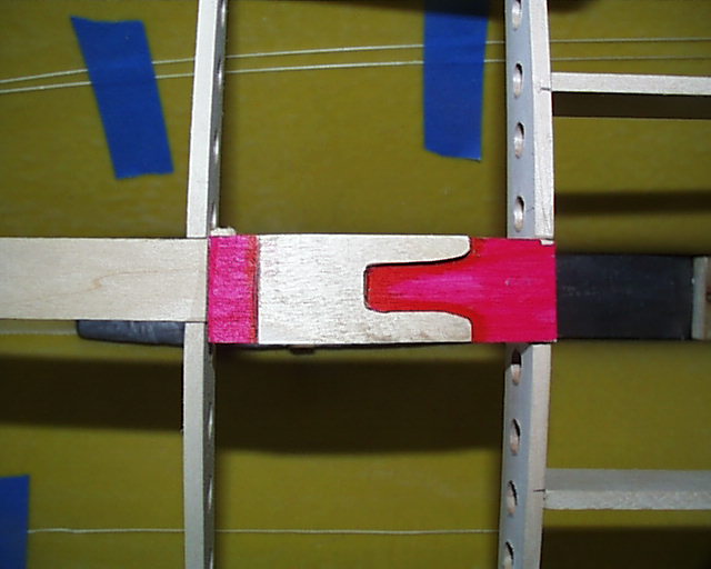
2002 Design The two photos below were during building that led to the changes in the Blueprint for the foredeck. Hot Pink was a leap of faith but has been doing just fine. The bow turning block is glued to the hull. It is suggested you go with Jamaica on the left for now and use station 8.5.
The king plank is installed from station 24 to 6. A smaller piece in fashioned into the bow over station 3.5. This will provide a more solid bow structure.
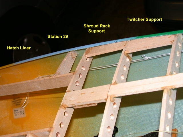
Connections continued... The hatch liner is 3/16" by 1" basswood. Cut these to fit. The opening is 4 inches on center forward and 5 inches aft. Glue these in.
Make partial ribs of 3/16" by 1" balsa to fit between the hatch liner and the hull flange at station 29. These are to be cut from the spare balsa 27.5 stringer. This is shown on the Blueprint and is to provide a backing anchor to the long Zellanack shroud rack. Glue these in position as you did with the stringers. They will be the aft supports for the shroud rack mounting planks.
Install and glue in the shroud rack mounting planks. These are 3/16" by 1" basswood. When installing the piece that ends at station 29, remember the racks are bolted in parallel to the centerline of the boat. The idea is that you want the bolt line for the racks close to center of the supporting planks.
The supports are installed between stations 24 and 29. The first one at 24 should go all the way to the sheer line under the flange, as the first bolt will be through the flange. To prevent stress on the deck sheet the supports are beveled to slide under the flange, while flush with the flange and the rib. It is a dirty job that needs to be done so go to it with the Dremel. It doesn't have to be pretty.
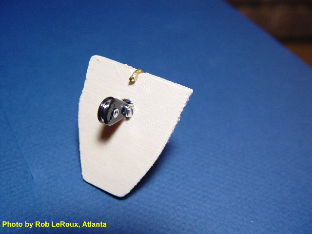
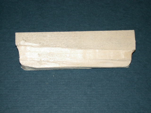
Mast Support And Strut Chock The mast step plank is 1/4" by 1" basswood with a 1/8" strut chock beneath. Fit and cut the plank to fit over the ledge at station 24 through 27.5. Glue the prepared compression strut chock to the underside as shown above. The piece shown above is upside down and the red marking is for relief to show the chock. The hilt position is based on a mast step at 25-1/2" on center. Clamp the plate to the plank with a paper clamp and glue the mast support plank into place with the chock facing down.
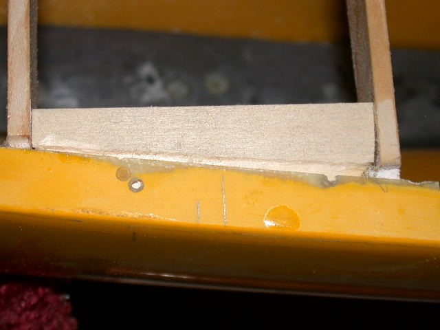
Twitcher Supports The supports for the twitcher exit guides are 3/16" by ¾" balsa. The jib exit guide is centerline at station 22 and the twitcher exit guides are 3-1/2" outboard of this. Cut, fit and glue in the supports.
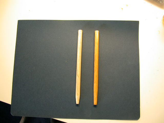
Cut a piece of 3/8" dowel a bit longer than you will need. Taper what will be the bottom to fit in the dimple on the ballast. If you did not put a dimple in, its okay. Now, start shortening the top till it will fit snuggly into the chock under the mast support plank. You do not want to force the deck frame upward, just snug. We use a sander down to the final fit.
Clean up the strut, seal and paint on two coats of Min-Wax with some sanding in between. It would be nice if it was fairly smooth as the main sheet line will lay lightly against it when taunt. Put it away till the decking process.
The Section Finish The structure should be sanded to smooth out the rough spots. A piece of the balsa sheeting can be used to search out these spots. Check all joints for security. Vacuumed and wipe clean the hull.
|