Sheetline System
![]()
![]()
![]()
![]()
![]()
![]()
![]()
![]()
![]()
![]()
![]()
![]()
![]()
![]()
![]()
![]()
![]()
|
Sheetline System
|
|
Last update, December 12, 2009 Installation of the Sheetlines
This page is for the Modern Build
Parts: SS Machine Screws and Nuts - 4-40 works, stock item Eye Bolt (3)- #144, MMY Eye Bolt (3)- #140, MMY Single Pulley - #250, MMY Single Deck Pulley - #253, MMY Dual Pulley - #254, MMY 1/16" bungee line - local fabric store Spectra Line - 80# Goodwind Some of the above parts have been mentioned and not installed Tools: Sharp Punch Drill Charge up your radio gear batteries Now that the ballast is in the hull you may like to build a simple servicing rack for the board. Working in the hull is easy but when the deck goes on removal is why this system was built.
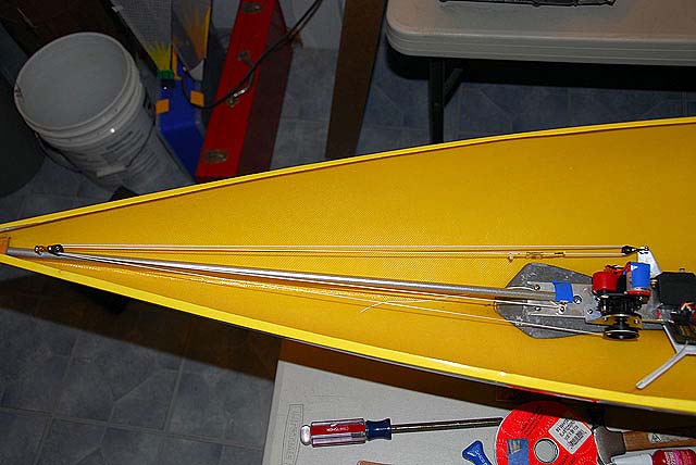
What you will do on this page is set up the winch and install the interior portion of the sheetline system and support components.
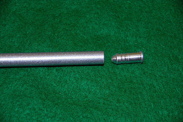
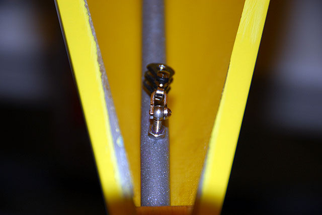
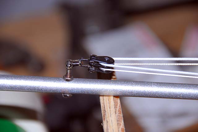
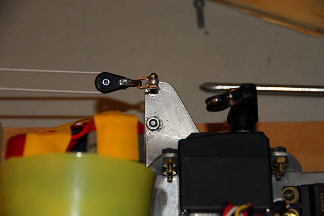
Turning Block Shaft An aluminum arrow head dummy point insert was forced into the arrow shaft to reinforce the wall where it would connect to the chassis. Then it was drilled for a 4-40 machine screw. Pretend a mounting of the shaft so you can trim the shaft to fit snugly in the wood retainer at the bow and with the bracket on the chassis. When you have sized the length you may want to sleeve the bow end just a bit to give add support to the dual pulley mounting screw.
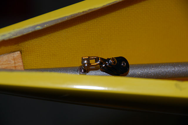
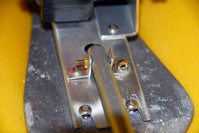
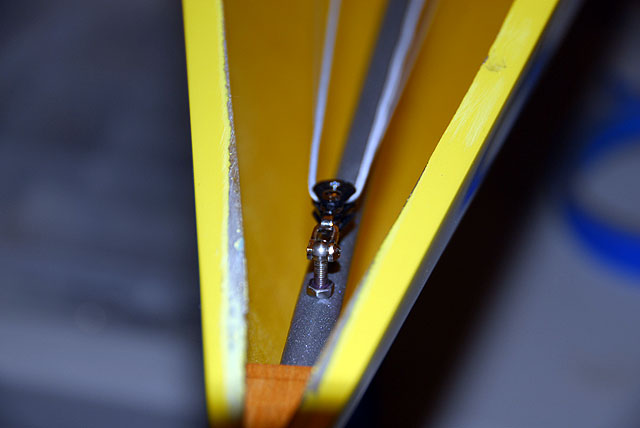
At the bow end and at a right angle to the mount the shaft was drilled to receive the long eyebolt you mounted the double pulley block earlier in another section. This should be about 3.5 to 4 inches from the bow. Install the block with nuts on both sides and with Loctite. Assemble the shaft to the two angle mounts as shown. Please note the head of the screw is on the starboard side. A stubby eyebolt was used to mount the port side bracket to the chassis. This eyebolt will be the anchor (or feed to and anchor) for the bungee line.
An arrow shaft was used here because it was in stock. Wood is okay but heavier and a CF tube would be okay if it had a thick wall. You see what needs to done so work it out.
Time out for a Winch, Radio and System Board Wiring Check Go to the Electronics section and to RMG Winch. Read all the RMG information. Do a systems check to know the System Board and radio gear is working properly. When you are satisfactorily finished return here.
Install the Winch Line Returning from the RMG Winch page mentioned above, It is expected the winch is set for counter-clockwise rotation of the drum from the full sheet out position...stick up to close haul.
The winch line is cut by sizing it from the drum, to the bow and to way past the rear of the chassis. Pass this line through the the hole provided on drum. Tie a figure eight knot with an over hand finish to lock the line inside the drum flange. Thread the line through the lower spindle of the bow dual turning block and drape it over the side of the starboard hull at the sheer.
Properly turn on the radio system. You know what you are supposed to hear. Place the winch stick full up (if it is not already there). When you know the winch is at full sheet out, stop.
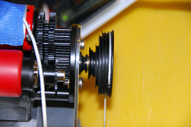
install the drum with the line direction forward with no wraps on the drum.
Hold the end of the line hanging over the boat to provide tension on the line to the drum. Start sheeting in the line to close haul. This line will not get to the small axle. Carefully slip off the drum so the wraps of line will not change in the grooves and rotate the drum counter-clockwise so the wraps will move down the spiral to the axis. When you get there watch till you are about a half wrap on the small diameter of the axis...slip the drum onto the drive as close to this as you can. This will give you about 4 clicks on the stick ratchet at close haul before the line starts up the spiral toward full sheet out.
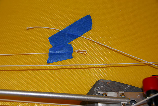
Mark the line with a pen about 3-1/2" from the outrigger block. Create a bowline loop for the collector with the knotted end near the mark. This does not need to be precise but not crowding the block either. Sheet out the winch holding tension on the line. The drum will look like this.
This will be the Delta set up because we want greater selections throughout the entire range of sheeting. Speed is not important. Just for you to check, sheet the line in and the spool will wind the line down onto the axle like you set it. Sheet it back out and tape the line to the hull for now.
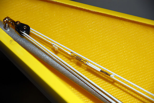
Bungee Line: 1/16" braided elastic was used for the bungee. One end was fed through the upper spindle at the bow, through the block on the outrigger and taped near the winch line loop. From the bow feed through the stubby eyebolt and taped as shown. That is your look. The bungee at the loop was tensioned forward and the winch line there pulled aft to tighten up the system and check the lines. None were touching. Cool!
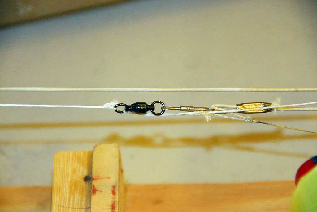
At the end coming from the outrigger block create a small loop in the bungee. Place a medium CL line connector the line collector and hook the bungee to it. An overhand knot was used to anchor the bungee to the stubby eyebolt at the end of the chassis beside the rudder servo with just a slight amount of tension on the line.
After field testing it was found there was twisting of the line in the collector area. A fishing swivel was introduced forward of the CL connector. Later the Jib sheet line will be connected to the swivel and the main sheet line to the aft end of the CL connector.
For cleanup electrical tape was placed over the axle nut for the shaft base and the soldering tabs on the back of the winch motor. Why not?
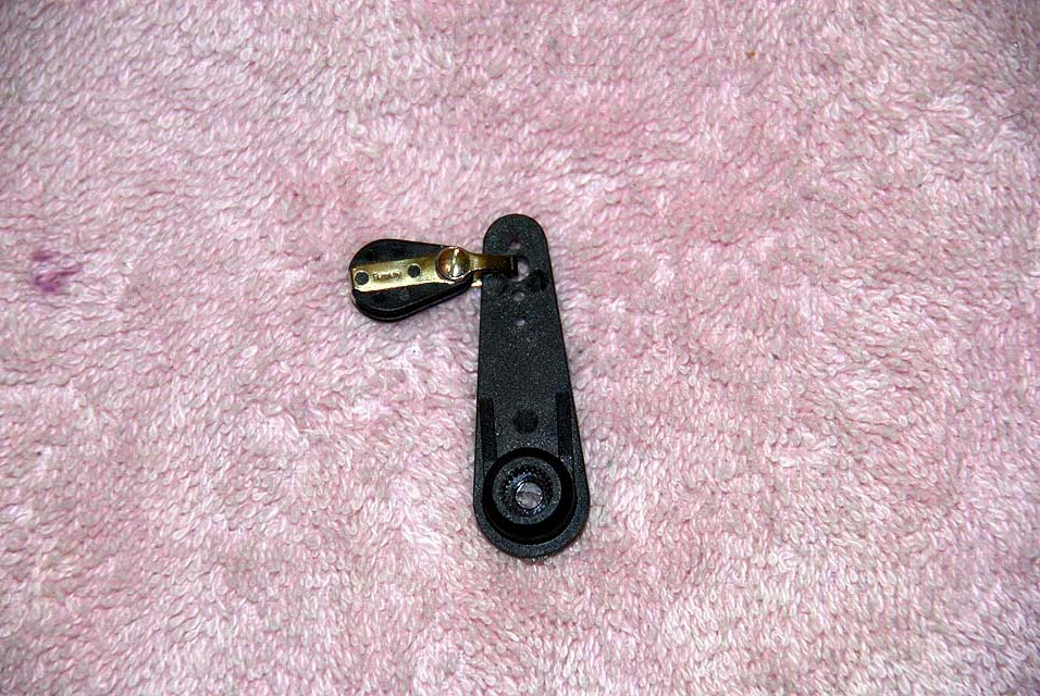
Jib Trim Servo Arm A new approach to the is being taken. The deck block is just too difficult and detailed for most to deal with using regular tools. This will be monitored to make sure it gives us reliability.
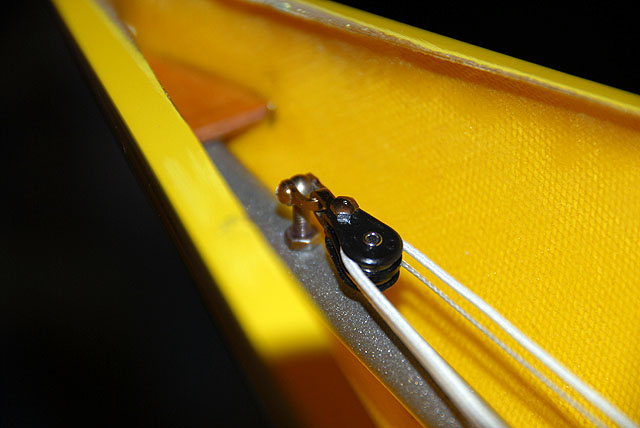
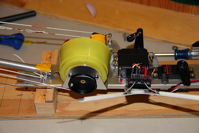
A 35mm heavy duty arm was used, which is longer then needed. The second hole down was used to prevent the block from spinning around. The hole was drilled so the small side of the shackle on the block would pass through. Install the block and that is all there is to that.
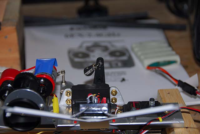
The 100 ounce torque servo produces about 150 degrees of travel and way more than needed. The vertical position was used for the neutral trim position on the TX knob. The 6EX has up/down arrows where the know replaced the gear switch. It is easy to see. When we get into the pre-tune phase adjustments will be made and the servo set to only that travel that will actually be used. This will make it easier on the water to select the trim you want and not over do it.
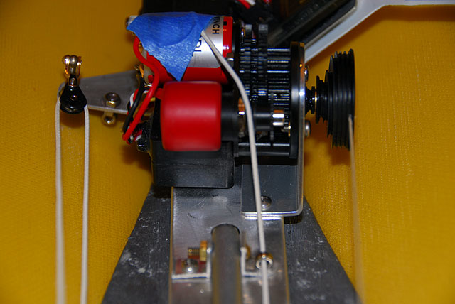
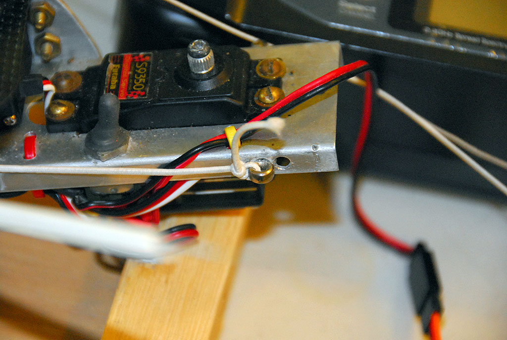
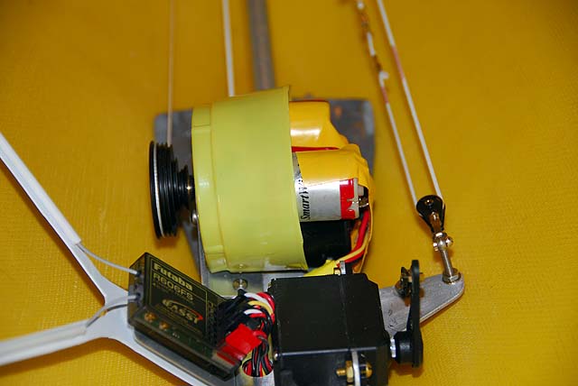
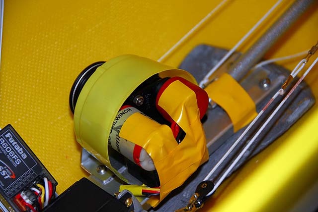
Sheetline Protections Despite chassis design and with loose sheetlines in mind stuff happens. The rudder tiller extension in on the port side away from the mainsheet line and the jib trim is outboard of the winch motor. The catch always is running to winch to full sheet out and there is no pressure on the booms to move. The lines go straight down.
What comes to the eye are three things, winch gears, motor solder tabs and looped wires and a nut on the sheetline shaft at the base. Pooling of the main sheetline just forward of the outrigger will be tested later when the line is attached to the collector. It will be hard for the jib sheetline to reach the gear but...
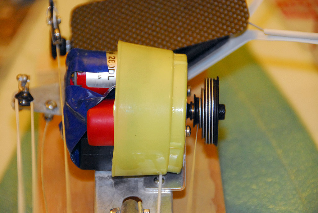
Tape was used for the motor area, as you can see. The same for the shaft. A plastic cup was used to fashion a shield over the gears and secured inside the winch mount. The gears were sprayed with AeroPlate before it was covered up. Aeroplate is a product of Aerotrend. It is reported this moisture protecting oil is not available and presently their site cannot be accessed. It is said that Boeshield T-9 will do the job. It has not been used here yet.
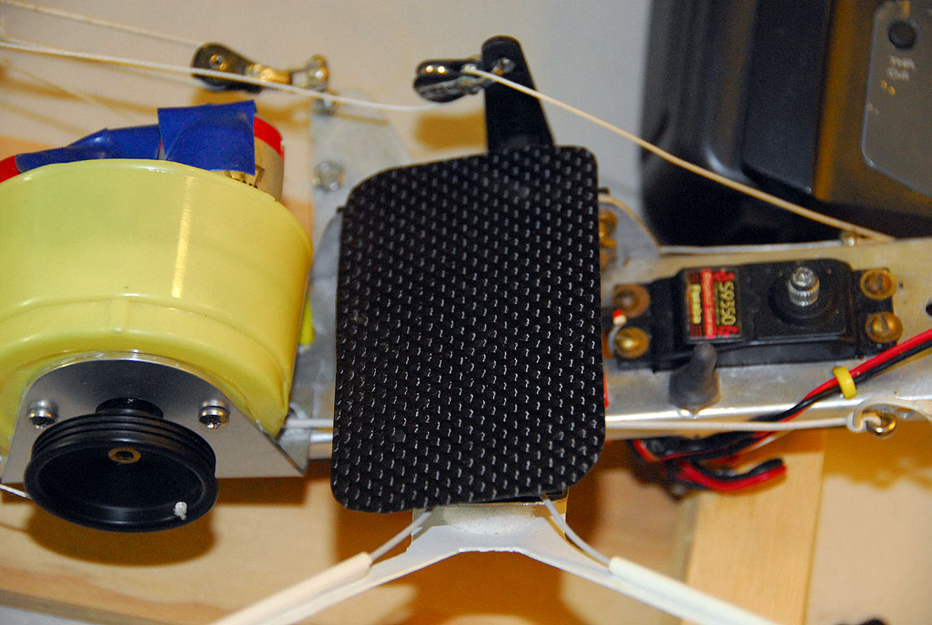
It was noted the RX is vulnerable to water from the hatch area and could drip on the RX. A thin piece of CF sheet was fashioned with Velcro to shield the RX.
The System Board is now complete and functioning. The lines to the booms will be attached after the deck goes on and the interior work is done.
You can move on to the EC to install the rudder and linkage. |